Aerostatic bearing and method for production thereof

A gas static pressure and bearing technology, which is applied in the field of manufacturing micro-holes and manufacturing the gas static pressure bearing, can solve the problems of limiting the maximum wall width, weakening the bearing plate, pressure difference, etc.

Inactive Publication Date: 2010-10-20
BSH BOSCH & SIEMENS HAUSGERAETE GMBH +1
View PDF1 Cites 14 Cited by
  • Summary
  • Abstract
  • Description
  • Claims
  • Application Information

AI Technical Summary

Problems solved by technology

However, in order to safely avoid mutual contact of the bearing bodies, a high density of nozzles is required at the same time, which severely weakens the bearing plate or limits the maximum achievable wall width due to the conical shape of the nozzles
[0005] A further disadvantage of the aerostatic bearing with conical nozzle geometry known from patent publication DE 44 36 156 C1 is that the gas flow through the nozzle is exclusively limited by the pressure difference generated across the nozzle and by the nozzle cross section

Method used


Image

  • Aerostatic bearing and method for production thereof
  • Aerostatic bearing and method for production thereof
  • Aerostatic bearing and method for production thereof

Examples


Embodiment Construction

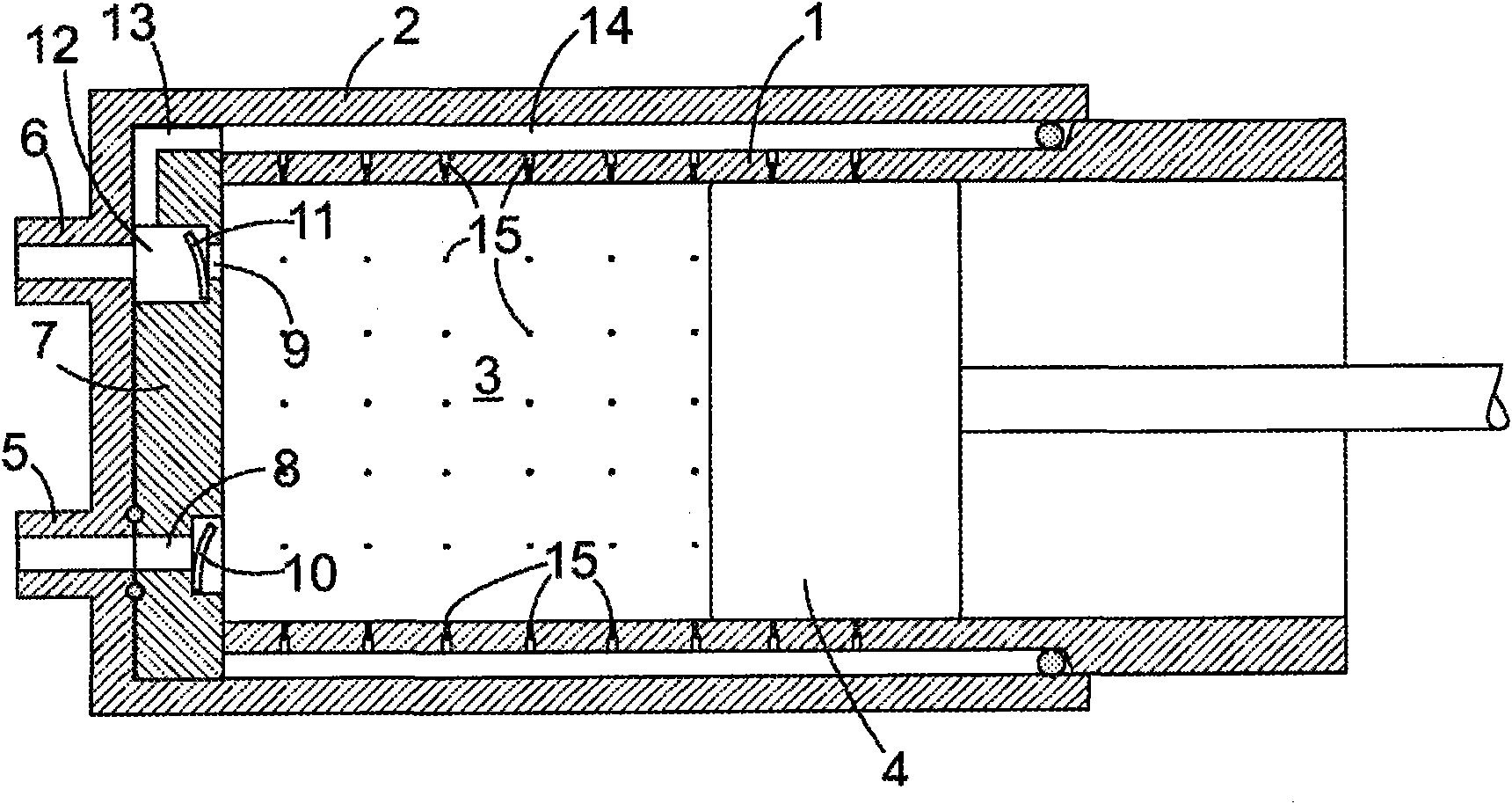
[0031] exist figure 1 The aerostatic bearing, shown in axial cutaway in , comprises a cylindrical pipe section 1, a cup 2 screwed around one end of said pipe section 1 (tube section 1 and cup 2 together define the compression chamber 3) and a piston 4 that can move backwards and forwards in the pipe section 1. An input connector 5 and an output connector 6 are arranged at the bottom of the cup holder. The valve plate 7 in the cup holder 2 forms the front side of the compression chamber 3 . The valve plate 7 comprises holes 8 , 9 aligned with the connections 5 , 6 , each hole accommodating a non-return valve 10 , 11 . The non-return valves 10, 11 are each formed by elastic tongues which, in the released position, sit against the valve seats formed by the shoulders of the holes 8 or 9, respectively; other configurations of non-return valves are also conceivable.

[0032] A connecting line 13 extends from a chamber 12 provided between the one-way valve 11 of the bore and the ...


PUM

PropertyMeasurementUnit
diameteraaaaaaaaaa
widthaaaaaaaaaa

Abstract

An aerostatic bearing comprises a guide element (1) provided with drillings (15) and a body (4) which may be moved along a surface of the guide element (1). The drillings (15) comprises a first section (16) adjacent to the body, of which at least a part region has an essentially constant cross-sectional area over the length thereof, which is less than a cross-sectional area of a region remote from the body.

Description

technical field [0001] The present invention relates to aerostatic bearings and to a method of producing micropores, which method can be used in particular for the production of said aerostatic bearings. Background technique [0002] Aerostatic bearings are based on air or other gas being blown between two bearing bodies. The resultant dynamic pressure means that a gap is created between the two bearing bodies, that is to say direct contact between the bearing bodies is avoided. A low-friction relative movement between the bearing bodies and thus a high-efficiency, low-wear bearing can thus be achieved. A supply channel for conveying air or another gas into the bearing gap runs through one of the two bearing bodies, referred to below as the guide element. In order to maintain the gas cushion between the bearing bodies, this supply must be done continuously. In order to keep the gas consumption of the bearing - and thus the energy consumption - low or to achieve a high bea...

Claims


Application Information

Patent Timeline
Patent Type & Authority Applications(China)
IPC IPC(8): B23K15/08F16C29/02F16C32/06
CPCF16C29/025B23K26/0626B23K26/388F16C32/0622B23K26/389
Inventor U·格拉夫J·奥斯特林斯凯A·沃尔夫M·贾基C·迈尔斯霍费尔J-G·舒伯特
Owner BSH BOSCH & SIEMENS HAUSGERAETE GMBH
Why Eureka
Try Eureka