Laser ranging device

A laser range finder and component technology, applied in the field of range finder, can solve the problems of poor test effect and affect the accuracy of the range finder, and achieve the effect of improving the accuracy of the test, being conducive to market competition, and improving the accuracy

Inactive Publication Date: 2010-10-27
聚能户外用品技术服务(深圳)有限公司
View PDF4 Cites 6 Cited by
  • Summary
  • Abstract
  • Description
  • Claims
  • Application Information

AI Technical Summary

Problems solved by technology

[0004] However, each component in the existing laser rangefinder is produced by division of labor, and the errors generated during production are inevitable, which makes the assembled rangefinder have errors of varying degrees, such as the existence of non-parallel laser light emitted or distance measurement. The reflected laser received by the instrument is not the strongest reflected laser, etc., which affects the accuracy of the distance test result of the rangefinder to the test object, and the test effect is poor

Method used


Image

  • Laser ranging device
  • Laser ranging device
  • Laser ranging device

Examples


Embodiment Construction

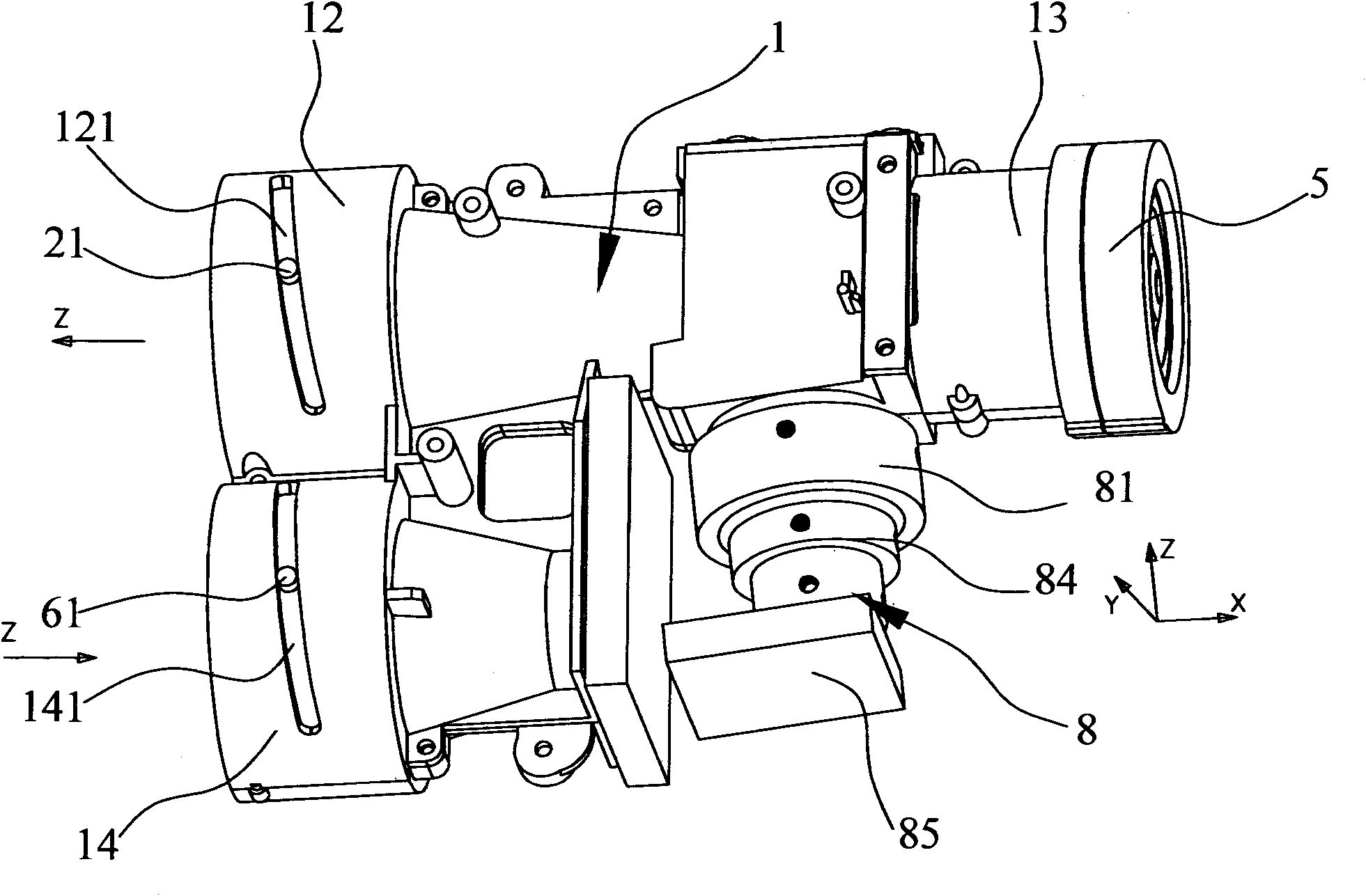
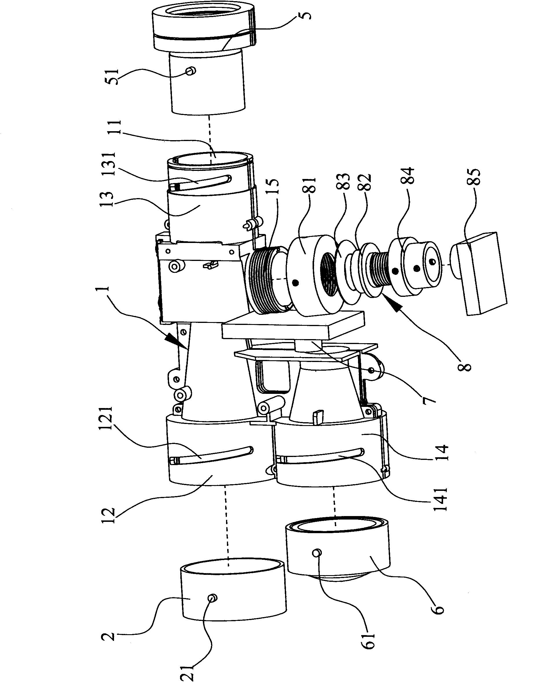
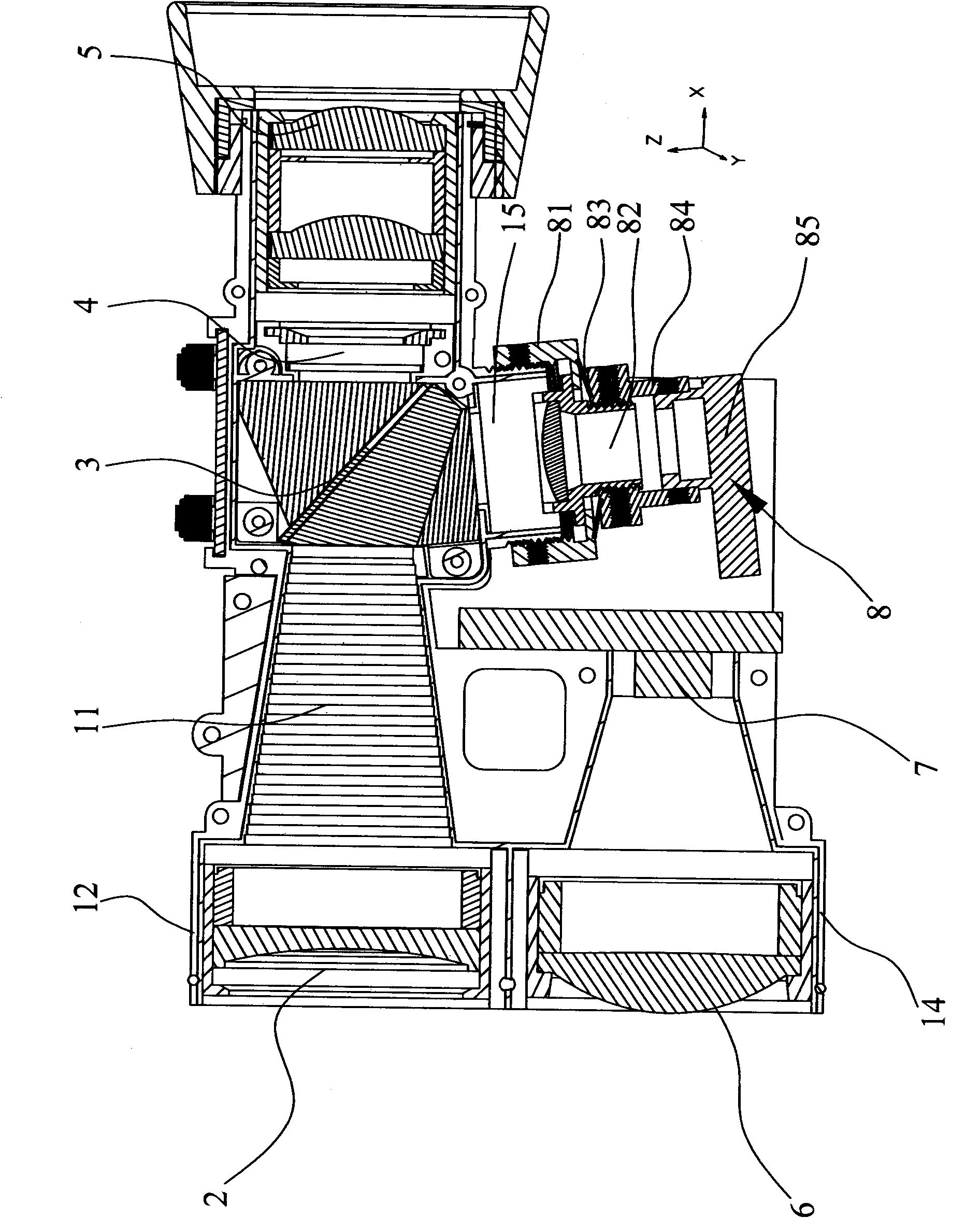
[0038] refer to Figure 1 to Figure 3 As shown, it shows the specific structure of the preferred embodiment of the present invention, including a main body 1 and an objective lens assembly 2, a prism assembly 3, an LCD display liquid crystal 4, an eyepiece assembly 5, and a receiving mirror assembly 6 arranged on the main body 1 , receiving tube 7 and transmitting module 8.

[0039] Specifically, wherein, the main body 1 is provided with an accommodating chamber 11, the accommodating chamber 11 is opened at both ends, and are respectively a first port 12 and a second port 13, and besides the first port 12, a third port is arranged side by side. port 14. The first port 12 is used for installing the objective lens assembly 2 , the second port 13 is used for installing the eyepiece assembly 5 , and the third port 14 is used for installing the receiving lens assembly 6 . A pair of first slanted slots 121 are disposed on the wall of the first port 12 , and the two first slanted s...


PUM


Abstract

The invention discloses a laser ranging device, comprising a body and an object lens assembly, a prism assembly, an eye lens assembly, a receiving lens assembly and an emission module which are arranged on the body, wherein the body is provided with a first port, a second port and a third port; the wall surfaces of the first port and the third port are respectively provided with a first skewed slot and a third skewed slot; the object lens assembly is sleeved in the first port; a first dowel on the outer surface of the object lens assembly is correspondingly buckled in the first skewed slot and stretches out of the wall surfaces of the ports; the receiving lens assembly is sleeved in the third port; a third dowel on the outer surface of the receiving lens assembly is buckled in the third skewed slot and stretches out of the wall surfaces of the ports; the emitted laser becomes parallel light by sliding the first dowel to change and adjust the displacement of the object lens assembly; the strongest reflected laser is received by sliding the third dowel to change and adjust the displacement of the receiving lens assembly, thus more accurately measuring the distance of the measured objects and improving the ranging accuracy.

Description

technical field [0001] The invention relates to the technology in the field of range finders, in particular to a laser range finder that can be adjusted to improve test accuracy. Background technique [0002] In addition to direct measurement with a ruler, the existing distance measurement method also includes the method of using a pole to measure with an instrument, and calculating the corresponding angle to calculate the distance. However, because the length of the ruler is limited, the ruler method is not suitable for long-distance measurement. The disadvantage of using a pole to measure with an instrument is that one person needs to insert the pole and another person controls the instrument, so this method is time-consuming. In the measurement of long distances, this method is inconvenient and prone to large errors. [0003] In recent years, the laser distance measurement method has been widely used in distance measurement, and the laser distance meter has also become a...

Claims


Application Information

Patent Timeline
Patent Type & Authority Applications(China)
IPC IPC(8): G01S7/481G01S17/08
Inventor 范立斌马平杜明辉袁仁坤雷欧杨晓东辜大光范振粤
Owner 聚能户外用品技术服务(深圳)有限公司
Why Eureka
Try Eureka