
Fuel cell with humidity control

A fuel cell and battery technology, applied in fuel cells, fuel cell additives, fuel cell grouping, etc., can solve the problems of complicated humidification device, increase of water vapor, and interruption of normal operation of batteries.

Inactive Publication Date: 2010-10-27
STMICROELECTRONICS (TOURS) SAS +1
View PDF5 Cites 2 Cited by
  • Summary
  • Abstract
  • Description
  • Claims
  • Application Information

AI Technical Summary

Problems solved by technology

Prior art humidification devices are generally more complex and, for example, also imply the addition of water vapor in the gas (air or oxygen and hydrogen) supplied to the battery
In addition, the measurement of the electrolyte moisture ratio generally requires interruption of the normal operation of the battery

Method used


Image

  • Fuel cell with humidity control
  • Fuel cell with humidity control
  • Fuel cell with humidity control

Examples


Embodiment Construction

[0025] For the sake of clarity, the same elements in different drawings have the same reference numerals, moreover, as is done in the representation of integrated components, the different drawings are not to scale.

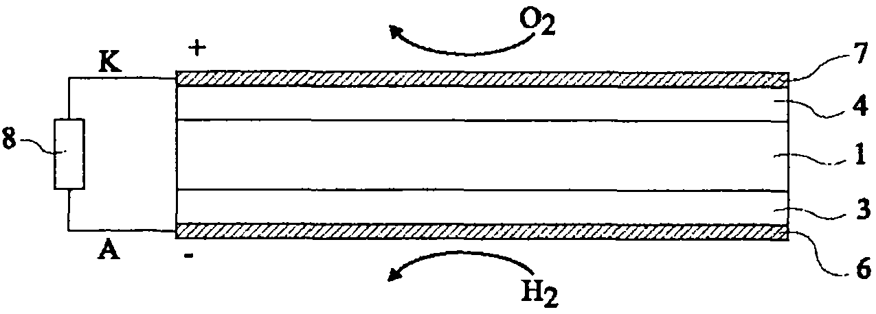
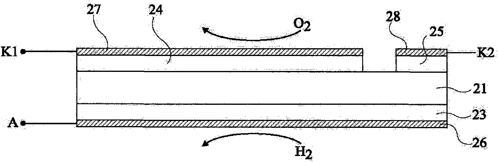
[0026] image 3 Highly schematically shown (similar to figure 1 ) A general structure of a fuel cell according to one embodiment of the present invention. The fuel cell is divided into a main cell and an auxiliary cell sharing the same electrolyte 21 . The lower surface side has a catalyst layer 23 and a conductive layer 26 . Arranged on the upper surface side are a first main catalyst layer 24 and a second subsidiary catalyst layer 25, which are separated and plated with metal plating layers 27 and 28, respectively. Thus, the battery comprises a single anode A and two cathodes K1 and K2. as combined below Figure 6 As explained, the cathode K2 is located, for example, on the periphery with respect to the cathode K1. Since the electrolyte is water permeable...


PUM


Abstract

A hydrogen-oxygen fuel cell including a main cell and an auxiliary cell sharing a common electrolyte and having at least one separate electrode, circuitry for measuring the humidity ratio of the electrolyte, and control and switching circuitry for operating the main and auxiliary cells in parallel on a same load or separately on two different loads.

Description

technical field [0001] This invention relates to fuel cells, particularly hydrogen-oxygen fuel cells, and more particularly to controlling the humidity of these cells. Background technique [0002] Such as figure 1 As shown, the oxyhydrogen fuel cell comprises a layer or sheet of electrolyte 1 sandwiched between two catalyst layers or sheets 3 and 4 plated with conductive layers 6 and 7 for making contact. The upper surface of the cell is in contact with oxygen (eg, ambient air), while the lower surface of the cell is in contact with hydrogen. [0003] In these cases, when the battery is connected to the load 8, a positive voltage appears on the upper surface side, or cathode, and a negative voltage appears on the lower surface side, or anode, and current flows through the load. On the anode side, the catalyst splits gaseous hydrogen molecules into two protons and two electrons, and the protons pass from the anode catalyst layer through the electrolyte layer to the cathode...

Claims


Application Information

Patent Timeline
Patent Type & Authority Applications(China)
IPC IPC(8): H01M8/24H02J7/00H01M50/77
CPCH01M2008/1095H01M8/04529Y02E60/521H01M8/0494H01M8/04656H01M8/1097H01M8/04291H01M8/1004H01M8/04947H01M8/04126H01M8/241Y02E60/50
Inventor 尼古拉斯·卡斯特皮埃尔·布伊隆耐莉·马丁奥德丽·马蒂耐恩特
Owner STMICROELECTRONICS (TOURS) SAS
Learn More