
Hearing aid system with feedback arrangement to predict and cancel acoustic feedback, method and use

A hearing aid and acoustic feedback technology, applied in hearing aid systems, generators of electrical probe signals, and compensating for acoustic feedback in hearing aid systems, can solve problems such as oscillations that cannot be easily established

Active Publication Date: 2010-10-27
OTICON
View PDF7 Cites 20 Cited by
  • Summary
  • Abstract
  • Description
  • Claims
  • Application Information

AI Technical Summary

Problems solved by technology

[0008] - frequency-shifting the signal from the input to the output of the amplifier such that an oscillation at a given frequency cannot be easily established; or

Method used


Image

  • Hearing aid system with feedback arrangement to predict and cancel acoustic feedback, method and use
  • Hearing aid system with feedback arrangement to predict and cancel acoustic feedback, method and use
  • Hearing aid system with feedback arrangement to predict and cancel acoustic feedback, method and use

Examples


Embodiment Construction

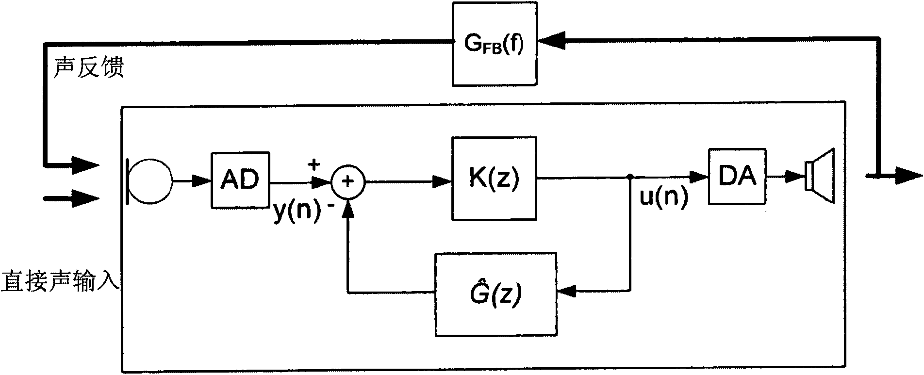
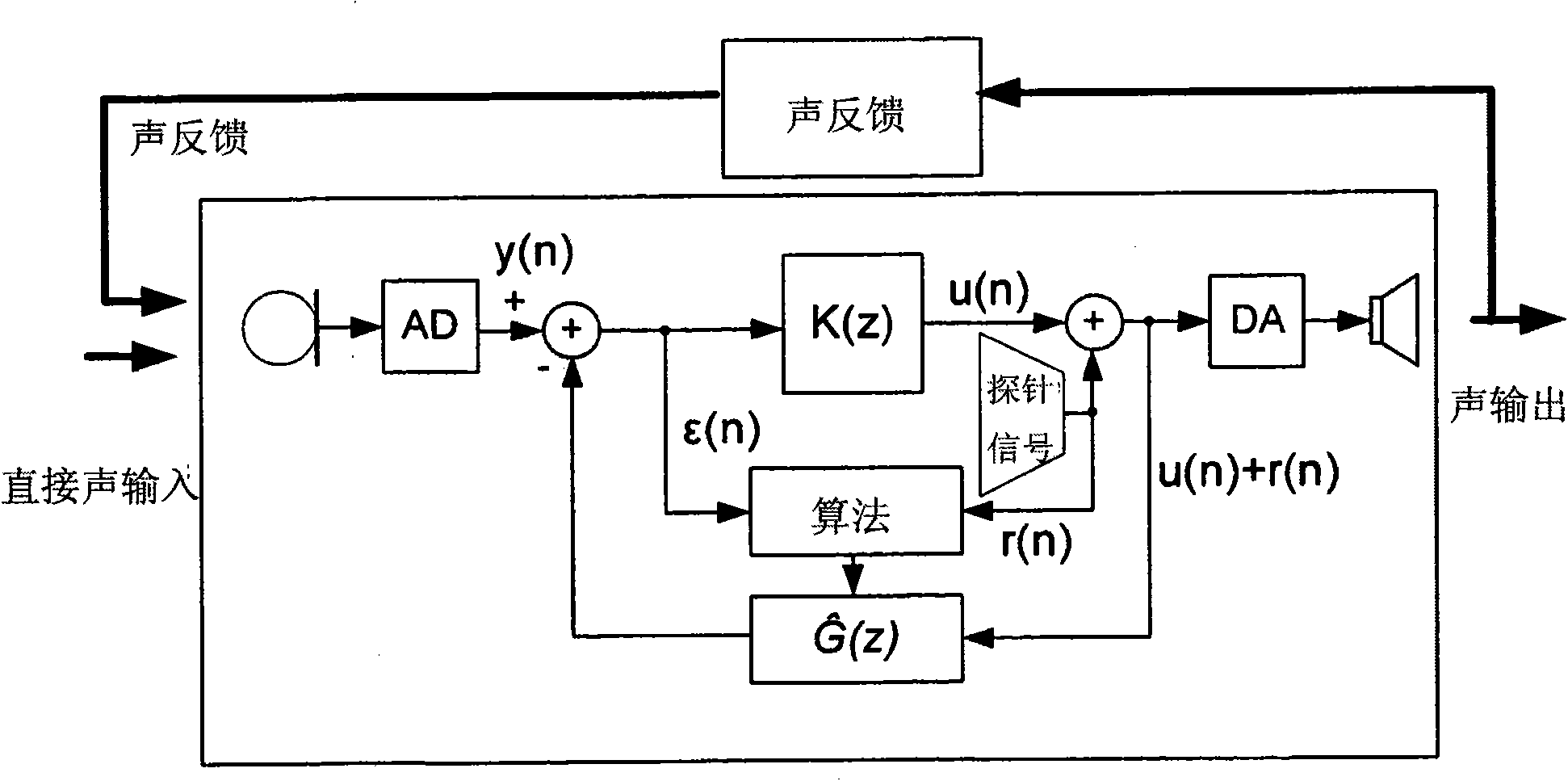
[0089] Figure 1a is a schematic illustration of a hearing aid system with a forward path, comprising a microphone for receiving acoustic input from the environment, an AD converter, a processing section K(z), a DA converter and for generating an acoustic output to the hearing aid wearer of speakers. Intentional signal pathways and components of the system are surrounded by dashed box lines. Specifies the (external, unintentional, frequency-dependent (f)) acoustic feedback path G from loudspeaker to microphone FB (f). exist Figure 1a In , the acoustic input from the acoustic feedback path is indicated as "acoustic feedback", and the acoustic input from other sources in the acoustic environment is marked as "direct acoustic input" (in Figure 1b and 1c is also similar).

[0090] Figure 1b shows the signal path and transfer function (including the external leakage path) of a prior art hearing aid system, including gain and phase responses with the aim of canceling the ext...


PUM


Abstract

The invention relates to a hearing aid system with an electrical feedback cancellation path, for compensating acoustic feedback between an output transducer and an input transducer by subtracting an estimate of the acoustical feedback from a signal on the input side of the amplifier part, the electrical feedback cancellation path comprising an adaptive filter for providing a variable filtering function. The invention further relates to a method of compensating acoustic feedback in a hearing aid system and to its use. The object of the present invention is to provide an alternative scheme for estimating the acoustical / mechanical feedback in a hearing aid. The problem is solved in that the hearing aid system comprises a second electrical input signal consisting essentially of the direct part of said first electrical input signal (i.e. without acoustic feedback), and wherein the second electrical input signal is used to influence, preferably enhance, the filtering function of the adaptive filter of the feedback cancellation path. Preferably, the system comprises a second input transducer for generating the second electrical input signal, the second input transducer being spatially located at a position where the amplitude of the acoustical signal from the output transducer at a given frequency is smaller than at the location of the first input transducer, and wherein the electrical signal of the second input transducer is used to adapt the filtering function of the adaptive filter. Preferably, the signal path comprises a generator of an electrical probe signal for use in characterizing the feedback path. The invention may e.g. be used in binaural hearing aid systems or in connection with other electronic devices comprising a second electrical input signal, e.g. generated by a microphone separately located from a first microphone of the hearing aid.

Description

technical field [0001] The present invention relates to hearing aids and in particular to a hearing aid system with improved feedback cancellation, optionally including a generator of electrical probe signals for characterizing the feedback path. [0002] The invention also relates to a method of compensating for acoustic feedback in a hearing aid system and to the use of a hearing aid system according to the invention. Background technique [0003] The following description of the prior art relates to acoustic feedback cancellation in digital hearing aids, one of the fields of application of the invention. It is well known that oscillations due to acoustic feedback (usually from external leakage paths) and / or mechanical vibrations in hearing aids can occur at any frequency with a loop gain greater than 1 (or 0dB in logarithmic representation), in other words, a forward gain greater than Leakage attenuation and phase shift around the loop are integer multiples of 360°. Fig...

Claims


Application Information

Patent Timeline
IPC IPC(8): H04R25/00
CPCH04R25/453
Inventor T·B·埃尔梅迪布J·赫尔格伦
Owner OTICON
Learn More