
DC-offset compensation loops for magnetic recording system

a compensation loop and magnetic recording technology, applied in the field of information storage, can solve the problems of degrading the performance of the data recovery system, adversely affecting the read channel gain, stability and overall quality, and its adoption, so as to reduce baseline wander and dc offset. , the effect of improving the signal processing circuitry

Inactive Publication Date: 2006-10-03
MARVELL INT LTD
View PDF14 Cites 93 Cited by
  • Summary
  • Abstract
  • Description
  • Claims
  • Application Information

AI Technical Summary

Benefits of technology

[0017]The present invention is directed to improved signal processing circuitry for reducing baseline wander and dc offset. To address the stated need and fulfill other desired objectives, in accordance with the invention, a communications read channel provides circuitry for remo

Problems solved by technology

However, problems associated with performing perpendicular recording have prevented its adoption.
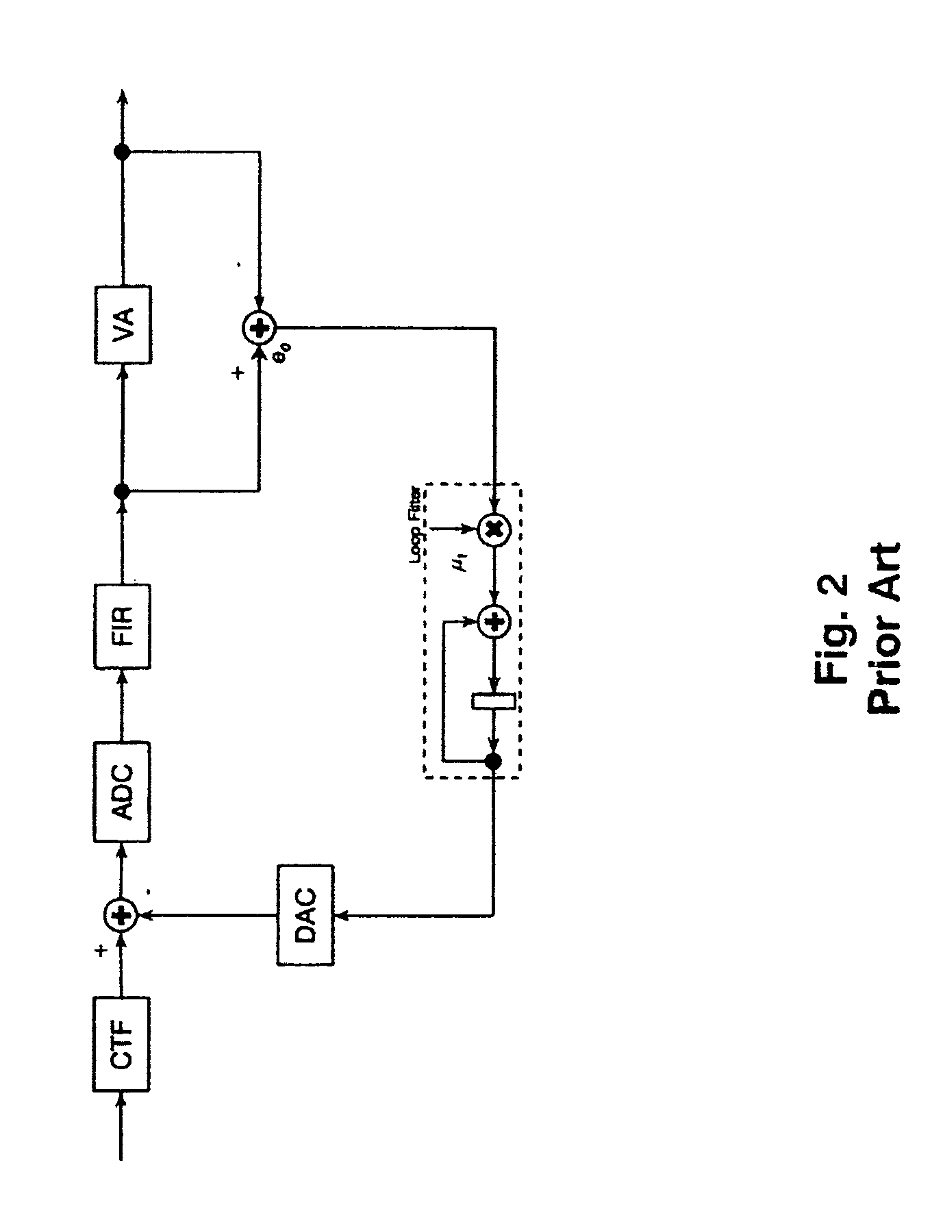
Analog signal processing circuitry, such as amplifiers, filters, and converters, introduces a dc offset that varies as a function of temperature and signal gain resulting in a signal level shift which, if uncorrected can degrade performance of the data recovery system.
The dc offset raises or lowers the normal peaks and valleys of the analog signal and the changing levels of the dc offset cause baseline wander that adversely affects the read channel gain, stability and overall quality.
This dc offset can be a problem for both longitudinal and perpendicular recording.
However, it does not remove any dc offset caused by digital signal processing.
One disadvantage of dc blocking is that the capacitors necessary for blocking the dc offset occupy considerable chip space, thereby making blocking unsuited for applications when a read channel is implemented on an integrated circuit.
Accordingly, blocking is not a very effective technique for handling dc offset in a read channel.
The current value of the dc correction signal results from delaying the biased error signal.

Method used


Image

  • DC-offset compensation loops for magnetic recording system
  • DC-offset compensation loops for magnetic recording system
  • DC-offset compensation loops for magnetic recording system

Examples


Embodiment Construction

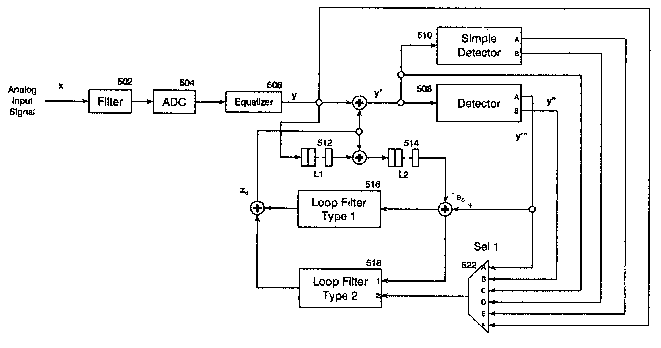
[0028]In a read channel for a magnetic recording system, a bit detector might be sensitive to a dc offset of the input signal when matched to a target that is not dc free. The analog circuitry and the high-pass filtering of a signal from perpendicular recording media are common sources of dc offsets. The dc offset caused by the analog circuitry is normally stationary and changes very little during a sector of data. The high-pass filtering due to lower high-pass cut-off corners used in perpendicular recording results in a faster varying dc offset. Therefore, the inventive circuit shown in FIG. 4 incorporates features to overcome the problem of dc offset caused by perpendicular recording.

[0029]In general, the inventive circuitry provides one or more feedback loops to correct the dc offset in the digital domain or in both the digital and analog domains. Each of the feedback loops comprises a loop filter having one or two loop inputs. The first type, shown in FIG. 9a, comprises a single...


PUM


Abstract

An apparatus, method, and system for providing dc offset reduction in a communications channel include two or more feedback loops to generate dc offset correction signals, which in turn are combined with an input analog signal and a processed digital signal thereby reducing dc offset. Each feedback loop may include an adaptive filter. At least one feedback loop may be responsive to an error signal that represents the difference between the delayed input of a first detector, and its output. Further, the dc offset correction signal, partially delayed, may be added to the error signal, thereby improving the response time of the dc offset correction loop.

Description

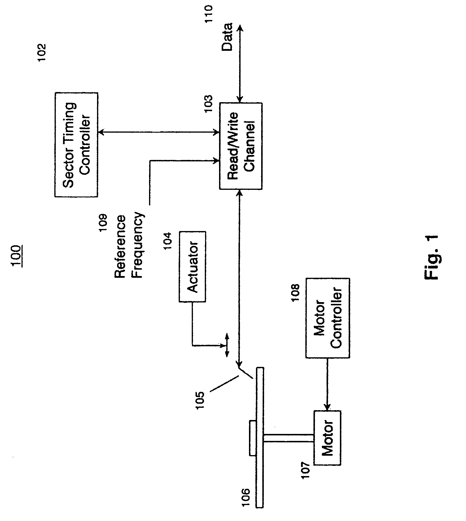
CROSS-REFERENCE TO RELATED APPLICATIONS[0001]This application claims the benefit of Provisional Application No. 60 / 457,613, filed Mar. 25, 2003 and Provisional Application No. 60 / 472,073, filed May 20, 2003. This application incorporates these provisional applications by reference.BACKGROUND OF THE INVENTION[0002]1. Field of the Invention[0003]This invention relates in general to the field of information storage, and more particularly to baseline wander correction and reduction of dc noise components in Hard Disk Drive (HDD) read channels.[0004]2. Description of the Related Art[0005]Hard disk drives (HDD) typically comprise at least one disk having a magnetic medium for storing information, a spindle, a controller for controlling disk rotational speed, a transducing head (for reading and writing data), a servo actuator assembly including a positioning controller for positioning the head over the appropriate disk track, and data channels for transmitting data to and from the disk. Th...

Claims


Application Information

Patent Timeline
IPC IPC(8): G11B20/10H03L5/00
CPCG11B20/10046G11B20/10203
Inventor OBERG, MATS
Owner MARVELL INT LTD
Learn More