Method for joint DC offset correction and channel coefficient estimation in a receiver

a receiver and channel coefficient technology, applied in the field of data receivers, can solve the problems of affecting the performance of the receiver, affecting the detection of transmitted data, and radio channel received signals also suffering from intersymbol interference (isi), and achieve the effect of reducing dc offs

Active Publication Date: 2005-04-21
MEDIATEK INC
View PDF7 Cites 17 Cited by
  • Summary
  • Abstract
  • Description
  • Claims
  • Application Information

AI Technical Summary

Benefits of technology

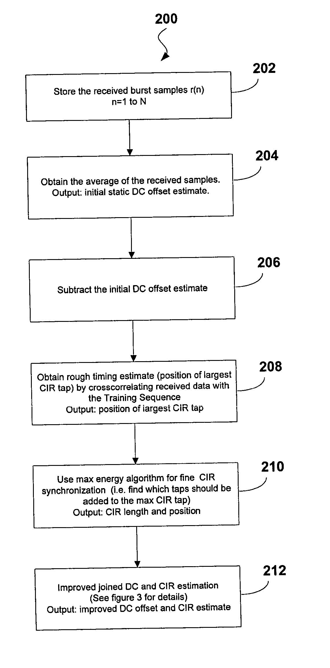
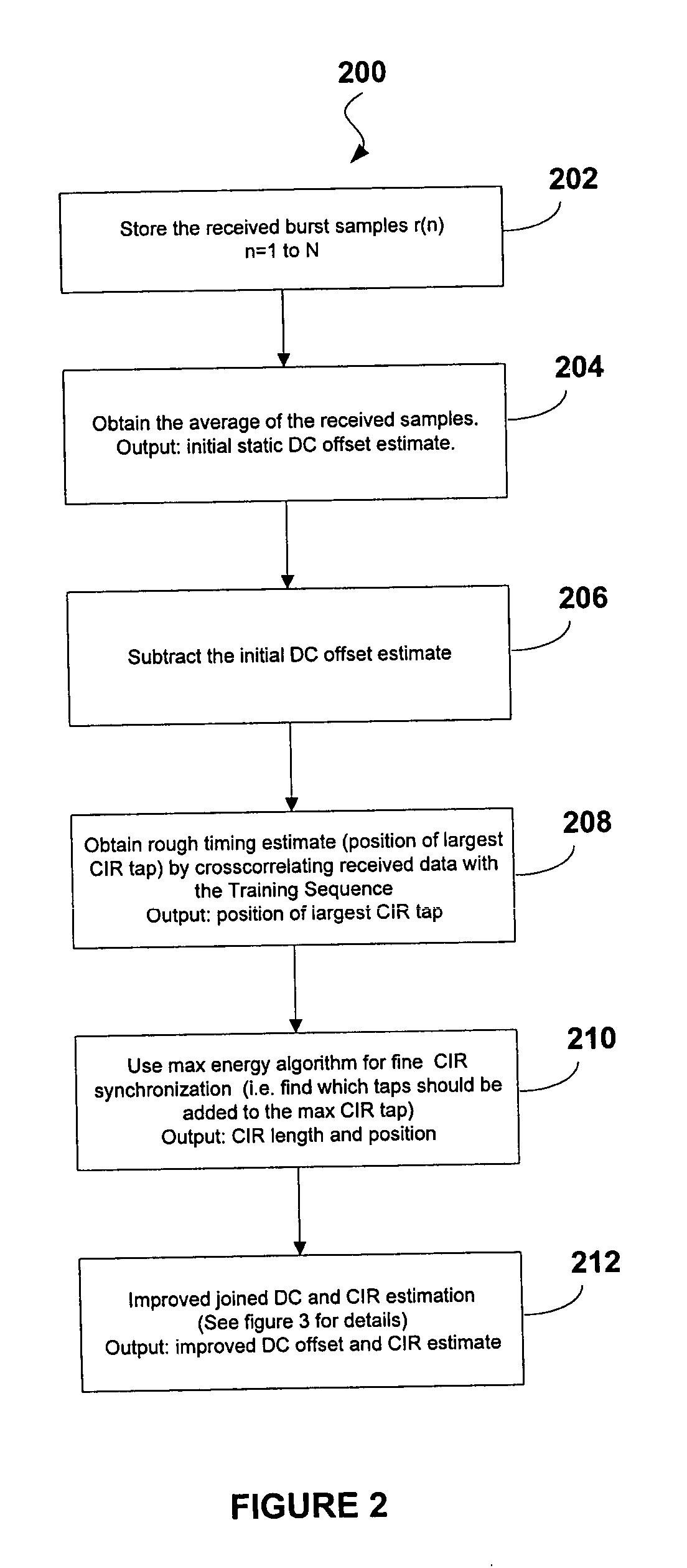
[0030] The present invention provides for a method for reducing DC offset associated with a receiver comprising the steps of: (a) receiving the received bust r(n); (b) storing the received burst samples, r(n), in a memory; (c) averaging said stored burst samples, r(n), and calculating an initial DC offset, A0, from the stored burst samples; (d) removing DC offset value from stored burst as follows: r(n)−A0; (e) identifying a rough timing estimate defining a position of largest channel impulse response (CIR) tap via cross-correlating stored burst data with a training sequence; (f) performing fine CIR synchronization to identify taps to be added to said identified largest CIR tap; (g) estimating an updated DC offset, A1, and a CIR, ĥ, via a perturbed LS CIR estimation where the received burst r(n) is modeled as follows: rj=∑i=0L-1⁢ ⁢hi⁢tj-i+fj⁢m+zj

Problems solved by technology

The basic challenge in detection of transmitted data comes from distortion caused by the channel.
While such direct conversion receivers offer the advantage of flexible architecture and educed cost, DC offset associated with such receivers is affecting the receiver performance.
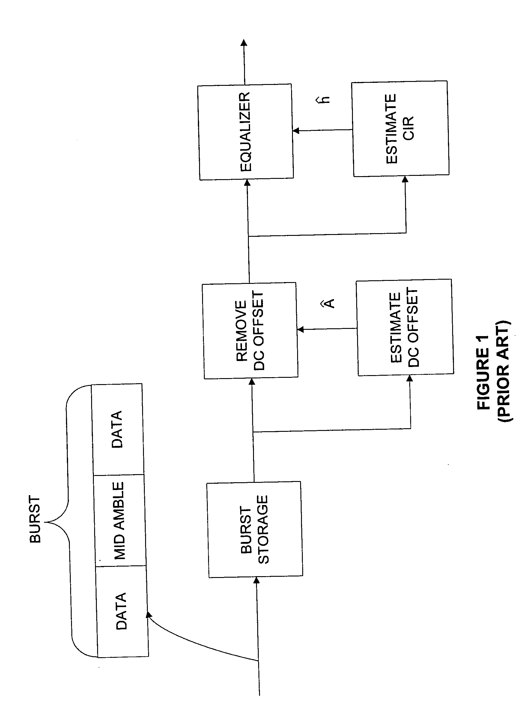
In such systems, the radio channels received signals also suffer from intersymbol interference (ISI) caused by multipath radio propagation and transmitter and / or receiver filtering.
The main limitation of cross-correlation CIR estimation is that it can only provide accurate estimates of up to 6 CIR taps.
Unlike the cross-correlation CIR estimation, the LS CIR estimation is a coupled problem.
Unfortunately, this procedure is very complex—about three to six times more complex than cross-correlation CIR estimation.
Furthermore, the simplest way to reduce the complexity of the CIR alignment step, by obtaining a rough LS CIR estimate consisting of 11 CIR taps, as with cross-correlation CIR estimation, results in a CIR estimation error that is far inferior to that achievable with cross-correlation CIR estimation.

Method used


Image

  • Method for joint DC offset correction and channel coefficient estimation in a receiver
  • Method for joint DC offset correction and channel coefficient estimation in a receiver
  • Method for joint DC offset correction and channel coefficient estimation in a receiver

Examples


Embodiment Construction

[0035] Although the present invention has been shown and described with respect to several preferred embodiments thereof, various changes, omissions, and additions to the form and detail thereof may be made therein without departing from the spirit and scope of the invention.

[0036] In Direct Conversion receivers DC offset is created by the self-mixing of either the received signal or the Local Oscillator (LO) signal. In case of the received signal, signal leakage causes self-coupling via the LO path. In case of the LO signal, leakage and reflection from the antenna allow a portion of the LO signal to couple via the signal path, resulting in self-mixing. Both mechanisms produce two components: one at DC and the other one at 2 times the carrier frequency. While the second component is removed by LP filtering, the DC component introduces DC offset, which, in some cases, can be very large. In general, the signal to DC offset ratio (expressed in dB) can be negative. LO-produced DC offse...


PUM


Abstract

Although DC offset reduction schemes can be applied in the analog domain, the residual static DCO in baseband is still present, significantly influencing the performance of high-level modulation schemes employed by recent high-data-rate wireless communications standards. In order to achieve satisfactory performance, DCO compensation algorithms are required in the digital domain. One such algorithm was developed which is based on joint estimation of the Channel Impulse Response (CIR) and the static DCO and ensures satisfactory performance of EDGE modem with direct conversion radio architectures. A further modification of the joint estimation algorithm, the so-called “perturbed joint L”, results in further improvement in the performance of the EDGE equalizer in critical fading channels.

Description

BACKGROUND OF THE INVENTION [0001] The invention relates to the field of data receivers, and, in particular, to systems and methods for reducing DC offsets in wireless receivers. [0002] The basic challenge in detection of transmitted data comes from distortion caused by the channel. Typically, channel refers to a combination of all non-ideal effects that adversely affect the ability to correctly detect the transmitted data sequence at the receiver. Such effects include, but are not limited to, effects of propagation (e.g. cable, radio channel etc.), non-linearities, or effects of transmit (TX) and receive (RX) filters. Current state-of-the-art detection techniques rely on the knowledge of the channel, which, therefore, must be estimated. [0003] The background of the invention will be described in the wireless communication scenario, although invention can be used in any communication system. As is known in the art, in wireless communications received radio frequency signals are conv...

Claims


Application Information

Patent Timeline
Patent Type & Authority Applications(United States)
IPC IPC(8): H04L25/02H04L25/06
CPCH04L25/0216H04L25/062H04L25/025H04L25/023
Inventor KOCIC, MARKOMARTINOT, LIDWINEZVONAR, ZORAN
Owner MEDIATEK INC
Why Eureka
Try Eureka