Method and apparatus for DC offset calibration

Active Publication Date: 2007-08-09
REALTEK SEMICON CORP +1
View PDF20 Cites 26 Cited by
  • Summary
  • Abstract
  • Description
  • Claims
  • Application Information

AI Technical Summary

Benefits of technology

[0010] In another aspect the invention provides A method of reducing DC offset in a radio frequency (RF) receiver, comprising effectively zeroing inputs to an amplifier in a chain of amplifiers; and commanding a change in current generation by a current generator associated with the amplifier based on a signal indicative of an output of the amplifier.

Problems solved by technology

Nevertheless, presence of DC offset may reduce the effective dynamic range of the receiver, and potentially can be sufficiently large that signal processing circuitry is unable to distinguish information in a received message.
Often DC offset is most pronounced with respect to leakage of a local oscillator signal, and may vary from receiver to receiver due to random variations in the manufacturing process resulting in different parasitic leakage levels.
Similarly, in the baseband amplification stage nonidealities in manufacture and variations of component characteristics with temperature may result in introduction of spurious DC components into a received signal.
In some such instances, recalibration or selection of different gain settings between frequency hops may be difficult in the allotted time.
In direct downconversion receivers, however, filtering of intermediate frequency is generally not available as the signal is generally downconverted directly to baseband.
However, SAW filters are often relatively large and expensive.

Method used


Image

  • Method and apparatus for DC offset calibration
  • Method and apparatus for DC offset calibration
  • Method and apparatus for DC offset calibration

Examples


Embodiment Construction

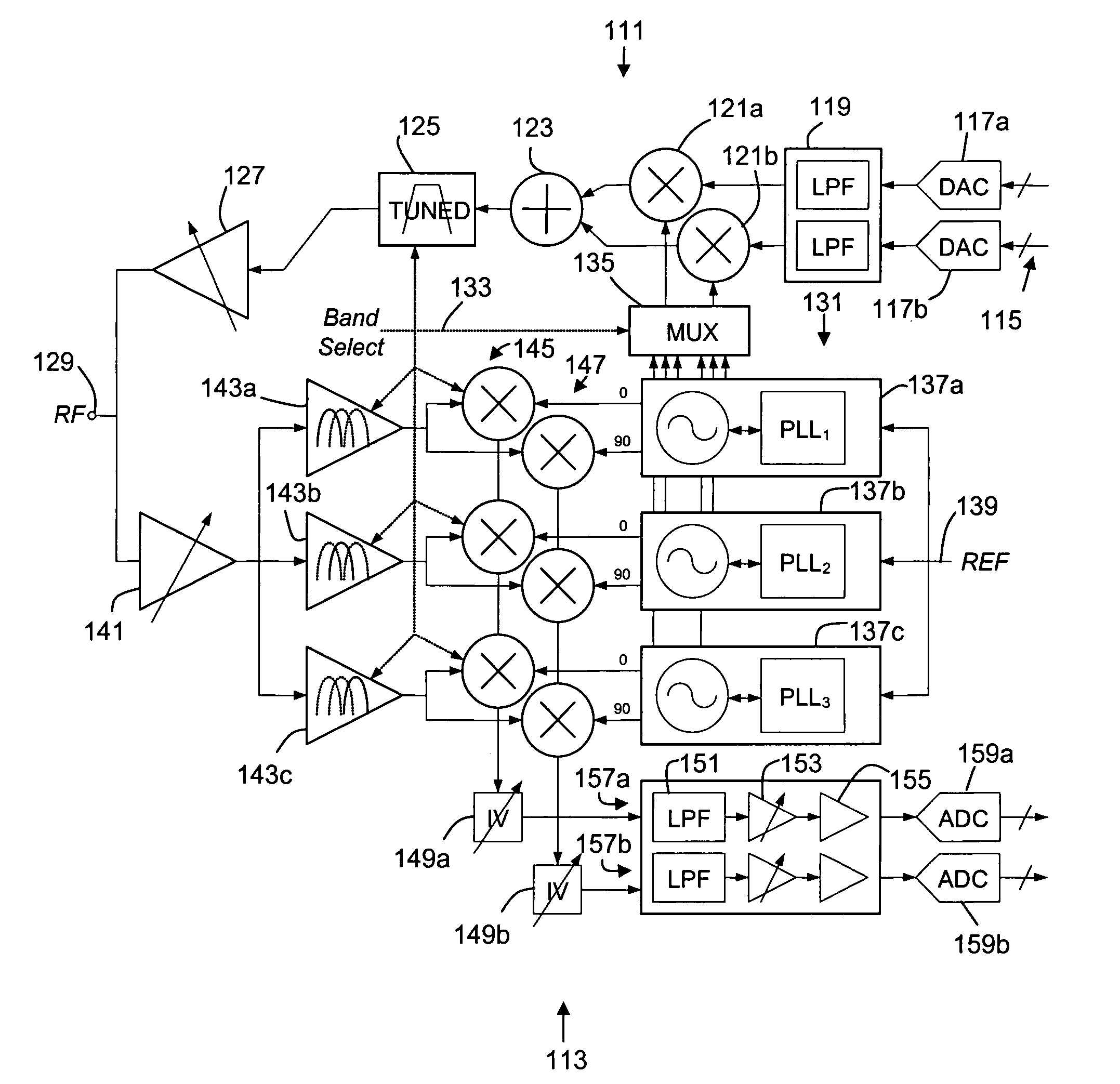
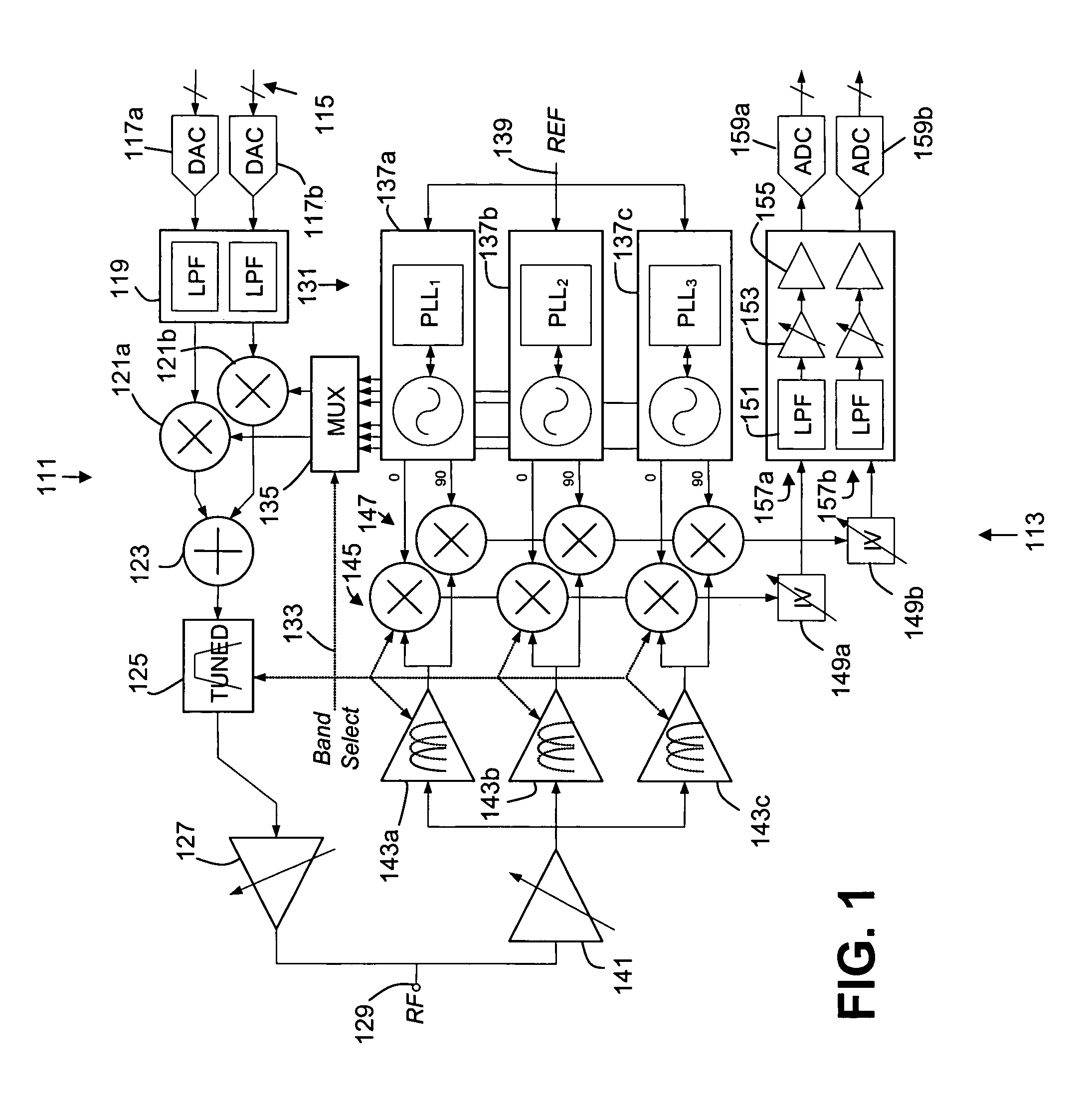
[0020]FIG. 1 shows an architecture for an RF transceiver. The RF transceiver includes a transmit chain 111 and a receive chain 113. Both the transmit chain and the receive chain includes circuitry for in-phase and quadrature components. Further, both the transmit chain and the receive chain are band selectable from a plurality of operational frequency bands, with the transmit and receive chains as shown both making use of a plurality of local oscillators, each providing mixing signals about a different frequency.

[0021] More particularly, the transmit chain receives analog in-phase and quadrature signals 115. The in-phase and quadrature signals are in digital form, and are converted to analog signals by digital to analog converters (DACs) 117a,b. The analog signals are passed through low pass filters 119 and provided to mixers 121a,b. The mixers mix the analog signals with a mixing signal to upconvert the analog signals, with the upconverted signals summed in a summer 123. The summe...


PUM


Abstract

A variable amplifier with adjustable current to correct for DC offset. The variable amplifier includes a zero function, allowing for zeroing of some amplifiers in an amplifier chain during correction for DC offset of another amplifier in an amplifier chain. In some embodiments selectable current injection is provided to an amplifier chain in conjunction with signals from selectable mixers.

Description

BACKGROUND [0001] The present invention relates generally to radio frequency (RF) receivers, and more particularly to removal of DC offset in a direct downconversion RF receiver. [0002] In many wireless communication formats no information is provided at DC, and DC offset may not directly corrupt received information. Nevertheless, presence of DC offset may reduce the effective dynamic range of the receiver, and potentially can be sufficiently large that signal processing circuitry is unable to distinguish information in a received message. Accordingly, RF receivers often include circuitry for reducing DC offset. [0003] DC offset may arise from a number of sources. These sources include DC offset caused by mixers and DC offset caused by nonidealities in the baseband amplification stage. DC offset from a mixer can arise, for example, due to leakage from one port of a mixer to another. Often DC offset is most pronounced with respect to leakage of a local oscillator signal, and may var...

Claims


Application Information

Patent Timeline
IPC IPC(8): H04B1/10
CPCH04B1/30
Inventor AYTUR, TURGUT
Owner REALTEK SEMICON CORP
Why Eureka
Try Eureka