Radio receivers

A radio receiver and circuit technology, applied in the field of zero-IF radio receiver equipment, can solve problems such as the reduction of receiver linearity, and achieve the effects of reducing DC offset, reducing noise, and reducing linearity

Inactive Publication Date: 2019-09-13
NORDIC SEMICONDUCTOR
View PDF4 Cites 3 Cited by
  • Summary
  • Abstract
  • Description
  • Claims
  • Application Information

AI Technical Summary

Problems solved by technology

However, this typically results in significantly lower overall receiver linearity, such as at the input-referred compression point (ICP) and Third-order intermodulation intercept point (IIP3) aspect

Method used


Image

  • Radio receivers
  • Radio receivers
  • Radio receivers

Examples


Embodiment Construction

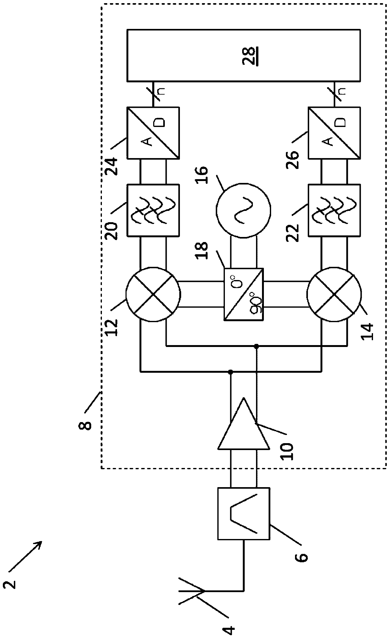
[0028] FIG. 1 is a block diagram of a conventional fully balanced zero-IF radio receiver architecture 2 . The radio receiver 2 includes an antenna 4 , an RF bandpass filter 6 and a radio frequency integrated circuit (RFIC) 8 . The RFIC 8 includes: a low noise amplifier (LNA) 10; two mixers 12, 14; a local oscillator 16; a quadrature phase shifter 18; two low pass filters 20, 22; , 26; and digital circuit 28. It is of course understood that the RFIC 8 may include other components (eg, RF transmitters), but these are not shown here for ease of illustration.

[0029] Antenna 4 picks up the RF signal, which passes through bandpass filter 6 , which provides an incoming balanced signal to LNA 10 . The LNA 10 amplifies the input signal and provides the amplified signal to two mixers 12 , 14 . Local oscillator 16 generates a local oscillator signal, which is used by phase shifter 18 to generate an in-phase (I) local oscillator signal and a quadrature (Q) local oscillator signal. A...


PUM


Abstract

A radio receiver device is arranged to receive an input voltage signal (VIN) at an input frequency and comprises: a first amplification circuit portion (110); a second amplification circuit portion (134); a current buffer circuit portion (140); and a down- mixer circuit portion (M1-M8). The first amplification circuit portion is arranged to amplify the input voltage signal to generate an amplifiedcurrent signal which is input to the current buffer circuit portion. The current buffer circuit portion has an input impedance (ZIN, B) and an output impedance (ZOUT, B), wherein the output impedanceis greater than the input impedance and is arranged to generate a buffered current signal. The down-mixer circuit portion is arranged to receive the buffered current signal and generate a down-converted current signal at a baseband frequency. The second amplification circuit portion is arranged to amplify the down-converted current signal to produce an output voltage signal (VOUTI, VOUTQ).

Description

technical field [0001] The invention relates to a radio receiver device, in particular a zero intermediate frequency radio receiver device. Background technique [0002] Radio Frequency (RF) receivers are found in many electronic devices, for example in modern wireless communication devices such as cellular telephones. Such RF receivers are usually highly integrated, with most of the various transceiver circuits integrated on a radio frequency integrated circuit (RFIC). Typically, such radio receivers are implemented using a so-called "zero intermediate frequency" (IF) architecture. Highly integrated resulting zero-IF architecture does not convert the received signal to an IF before further conversion to baseband as in other traditional radio receiver architectures, but uses a single down-converting mixer to convert the input signal for the baseband. Zero-IF architectures are particularly popular for their low bill of materials (BOM), low cost and associated especially lo...

Claims


Application Information

Patent Timeline
Patent Type & Authority Applications(China)
IPC IPC(8): H04B1/30H03D7/14H04B1/00
CPCH03D7/1441H03D7/1458H03D7/1466H03D7/165H03D2200/0082H03F3/195H03F3/45475H04B1/30H04B1/16
Inventor 皮特·斯文恩
Owner NORDIC SEMICONDUCTOR
Why Eureka
Try Eureka