Self-oscillating amplifier with high order loop filter

a loop filter and self-oscillating technology, applied in the direction of amplifiers, low frequency amplifiers, electric devices, etc., can solve the problems of residuals in the connecting cable, inability to perfect demodulation, and distortion of the switching power stag

Active Publication Date: 2018-12-25
ICEPOWER
View PDF9 Cites 2 Cited by
  • Summary
  • Abstract
  • Description
  • Claims
  • Application Information

AI Technical Summary

Benefits of technology

[0010]It is therefore an object of the present invention to provide a self-oscillating amplifier system which alleviates all or at least some of the above-discussed drawbacks of the presently known systems.
[0017]The present invention is based on the realization that currently available systems have limited loop gain at high frequencies (e.g. 18-20 kHz) and that they also exhibit stability issues, in the form of high phase turn at low frequencies, in particular for systems which include a DC-servo loop. Moreover, the inventors realized that the second order demodulation filter, in particular the second order poles of the demodulation filter need to be compensated for in self-oscillating amplifier systems. Thus, by providing a high order forward filter in the system, a forward filter which includes a second order pole pair and second order zero pair, one can construct a system with less phase turn at low frequencies, steep cut-off after the desired bandwidth which results in a high loop gain in the self-oscillating loop within the audio band, and also compensate for the demodulation filter poles.
[0018]In one exemplary embodiment the self-oscillating amplifier system further comprises a DC-servo loop and a switch to couple a gain into the DC-servo loop from an output of the compensator. The DC-servo loop is used to reduce DC-offset at the output of the system, and can furthermore be used to minimize an audible pop at the output during start-up of the system. The forward filter improves the stability of the system when a DC-servo is used since there is less phase turn at low frequencies. Low phase turn is preferable for stability reasons when having a gain from the compensator as input to the DC-servo included in the DC-servo loop. Thus, the DC-servo receives input from the output of the demodulation filter and from an output of the compensator and then generates a DC-servo output to the system input.
[0020]In another exemplary embodiment the compensator further includes a second forward filter which is a low-pass filter. This second forward filter compensates for the limited high frequency gain of the first forward filter.

Problems solved by technology

The challenges in switching amplifier design relates to the fact that PWM is in effect a multiplication / mixing between the input and power supply variable, this is equivalent to zero power supply rejection.
The switching power stage causes distortion from numerous contributions since power Metal-Oxide-Semiconductor field-effect transistors (MOSFETs) have parasitics and need to be driven by differentiated turn-off / turn-on delays.
Perfect demodulation is not possible, leaving residuals in the connecting cables.
Achieving Robust Stability & Excellent audio performance is many times a very complicated task, given the real world and test bench parameter space for load perturbations, input stimuli and power supply range.

Method used


Image

  • Self-oscillating amplifier with high order loop filter
  • Self-oscillating amplifier with high order loop filter
  • Self-oscillating amplifier with high order loop filter

Examples


Embodiment Construction

[0033]In the following detailed description, preferred embodiments of the present invention will be described. However, it is to be understood that features of the different embodiments are exchangeable between the embodiments and may be combined in different ways, unless anything else is specifically indicated. Even though in the following description, numerous specific details are set forth to provide a more thorough understanding of the present invention, it will be apparent to one skilled in the art that the present invention may be practiced without these specific details. In other instances, well known constructions or functions are not described in detail, so as not to obscure the present invention.

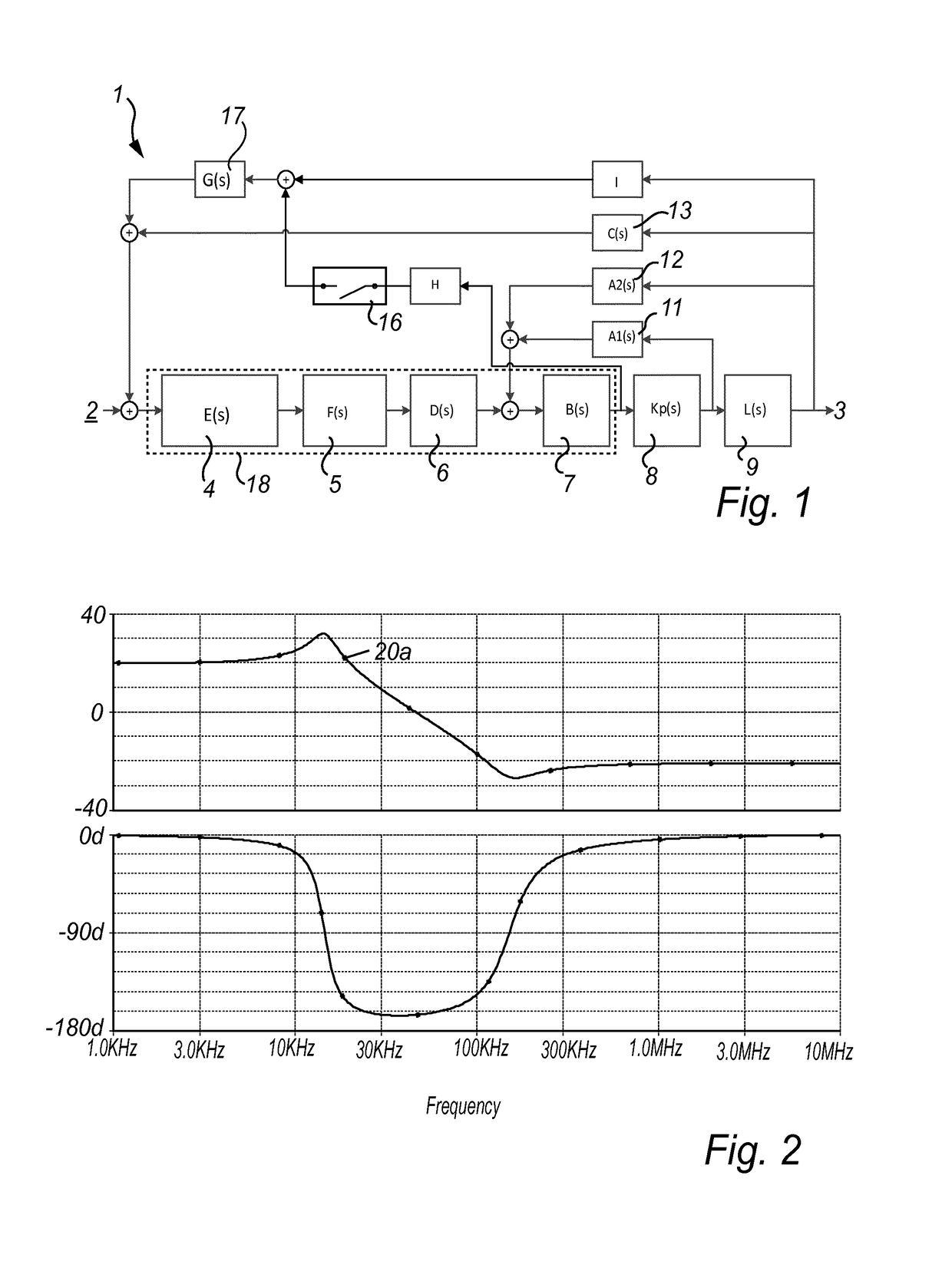
[0034]FIG. 1 illustrates a block-diagram representation of a self-oscillating amplifier system 1 in accordance with an embodiment of the invention. The system 1 comprises a set of compensator 18 forward blocks 4, 5, 6 and 7 each having a transfer function E(s), F(s), D(s) and B(s) ...


PUM


Abstract

A self-oscillating amplifier system is disclosed. The system comprises a pulse modulator, a switching power amplification stage and a demodulation filter. Moreover, the system comprises a compensator including a forward filter which is a high order filter including a second order pole pair and a second order zero pair. Hereby it is possible to decrease the phase turn at low frequencies for better stability and increasing the gain of the control loop within the desired bandwidth.

Description

[0001]This patent application is a U.S. national stage filing under 35 U.S.C. § 371 of International Application No. PCT / EP2015 / 077929 filed Nov. 27, 2015 (published as WO 2016 / 091620 on Jun. 16, 2016), which claims priority of Denmark Application No. PA201400713 filed Dec. 8, 2014 and Denmark Application No. PA201500358 filed Jun. 22, 2015. The disclosures of the applications identified in this paragraph are incorporated herein by reference in their entirety.FIELD OF THE INVENTION[0002]This invention relates to the field of DC-DC and DC-AC power conversion, with particular relevance for high definition switching audio power amplification.BACKGROUND OF THE INVENTION[0003]Switching Class D audio amplifiers have found increasing use in the industry in recent years, due to the improvements in output stage switching devices and equally in modulation and feedback control methods. The classical switching power amplifier system consists of a pulse modulator, for converting an analog or dig...

Claims


Application Information

Patent Timeline
Patent Type & Authority Patents(United States)
IPC IPC(8): H03F1/26H03F3/217H03F3/183
CPCH03F1/26H03F3/183H03F3/217H03F2200/171H03F2200/03H03F2200/129
Inventor ANDERSEN, KENNET SKOV
Owner ICEPOWER
Why Eureka
Try Eureka