
Intelligent earthquake bed

An intelligent, bed frame technology, applied in bed frames, instruments, other seating furniture, etc., can solve the problems of complex structure, unstable working performance, low degree of automation, etc., and achieve good safety performance, simple structure, and working stability. Good results

Inactive Publication Date: 2010-11-03
LIYANG CITY ZHENGXIANG PRECISION MACHINERY
View PDF5 Cites 28 Cited by
  • Summary
  • Abstract
  • Description
  • Claims
  • Application Information

AI Technical Summary

Problems solved by technology

[0005] The above scheme has realized the anti-shock effect to a certain extent, but there are technical problems such as complex structure, unstable working performance, and low degree of automation.

Method used


Image

  • Intelligent earthquake bed
  • Intelligent earthquake bed
  • Intelligent earthquake bed

Examples


Embodiment 1

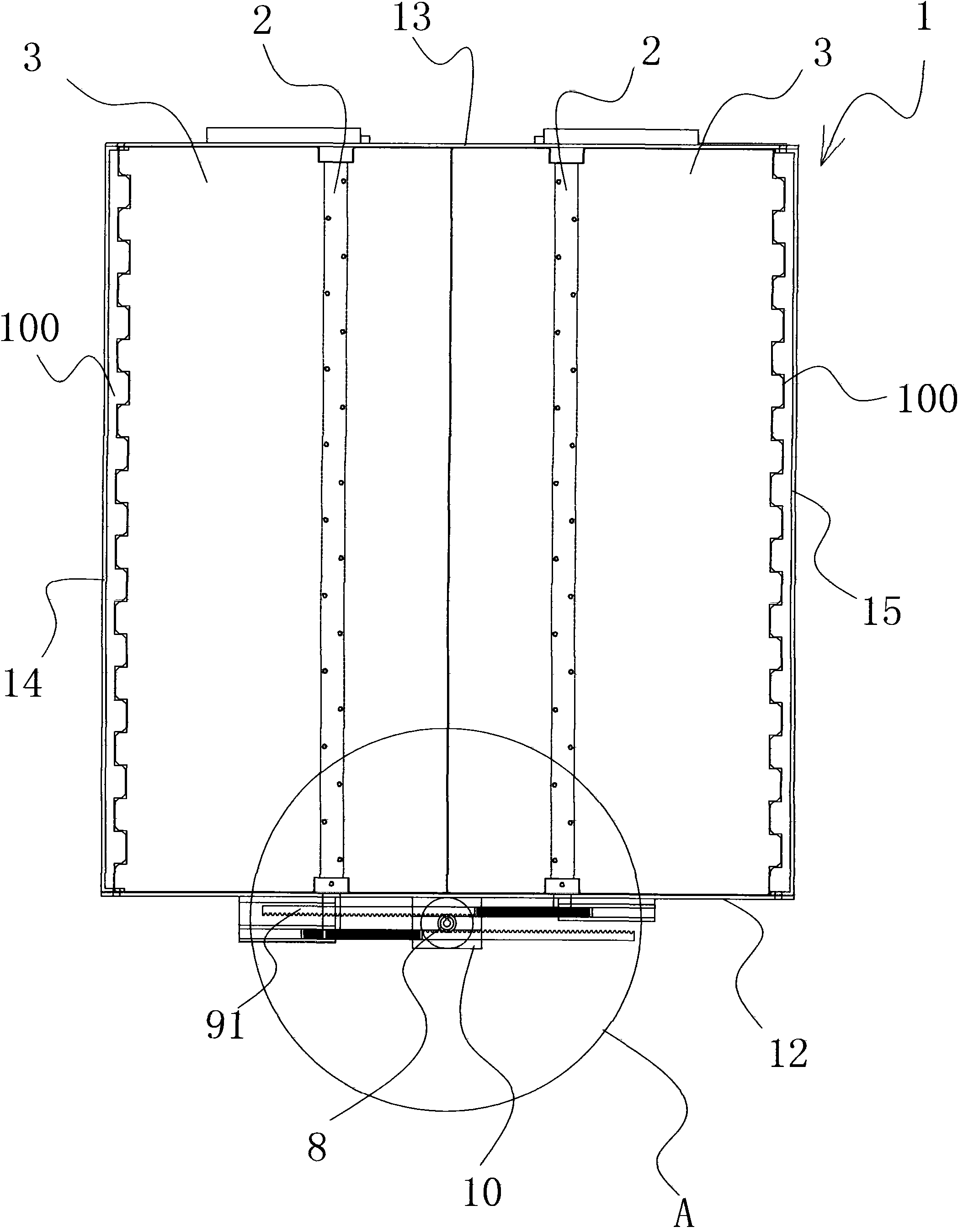
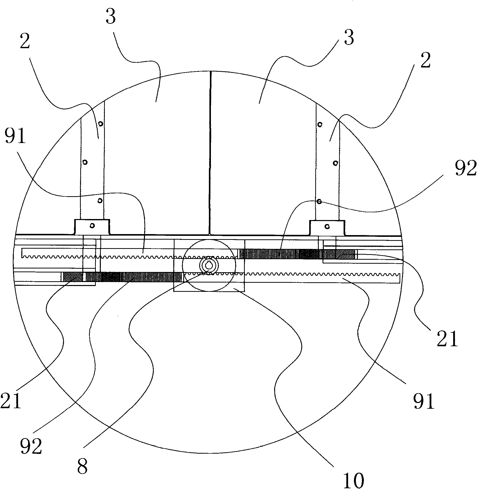
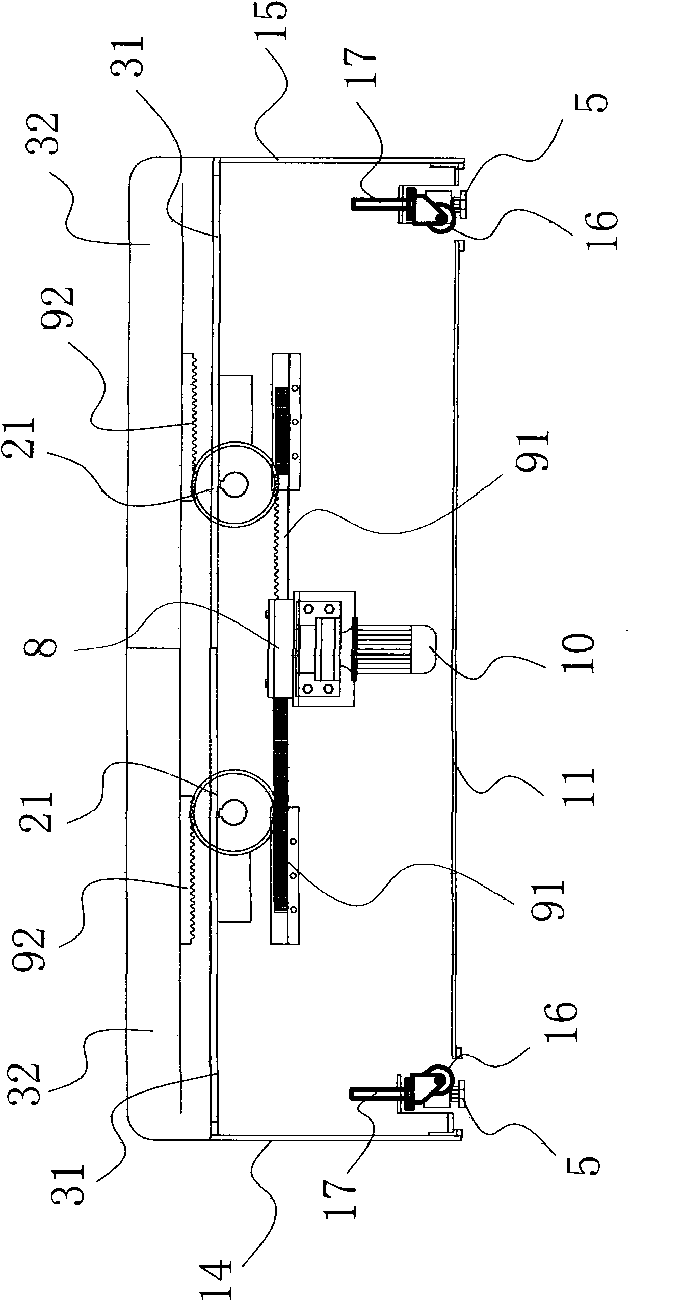
[0030] Such as Figure 1-4 As shown, the intelligent anti-vibration bed includes a bed frame 1, and the bed frame 1 includes a rectangular base plate 11, and four sides of the base plate 11 are respectively fixed with a front side plate 12, a rear side plate 13, a left side plate 14 and a right side plate 15. The bed frame 1 is provided with two rotatable bed board shafts 2 arranged along the long axis of the bed frame 1 , and a bed board 3 is respectively fixed on each bed board shaft 2 . The left side plate 14 coincides with the side of the bed board 3 through a concavo-convex structure 100 , and the right side plate 15 coincides with the side of the bed board 3 through another concavo-convex structure 100 . The bed board 3 includes a board body 31 and a mattress 32 fixed on the board body 31 . The bottom of the bed frame 1 is also provided with several rollers 16 to facilitate the movement of the bed frame 1, each roller 16 is arranged on a screw rod 17, and the screw rod ...

Embodiment 2

[0035] Such as Figure 5-7 As shown, in this implementation, the power mechanism includes two groups of driving devices 20 with symmetrical structures and one-to-one correspondence with the bed board 3, and each group of driving devices 20 includes a motor 201, a central gear 202, a guide seat 203, and a first rack 204, respectively. and the second rack 205. The guide seat 203 is fixed on the back of the bed board 3 and the central gear 202 is located in the guide seat 203 , and the central gear 202 is fixedly connected with the output shaft of the motor 201 . One end of the first rack 204 and the second rack 205 are meshed with the central gear 202 respectively, and the other end of the first rack 204 is hinged with the bed frame 1, and the other end of the second rack 205 is connected with the bed frame 1 hinged. The motor 201 is fixed on the guide seat 203 .

[0036] The left side plate 14 coincides with the side of the bed plate 3 through the concave-convex structure 10...


PUM


Abstract

The invention belongs to the technical field of safety devices for earthquake disasters, and relates to an intelligent earthquake bed which solves the technical problems of complicated structure, low work stability and the like in the prior art. The earthquake bed comprises a bedstead, wherein two bed board shafts which are distributed along a long shaft of the bedstead are arranged on the bedstead; a bed board is fixed on each bed board shaft; a power mechanism capable of enabling two bed boards to rotate in an opposite direction and enabling a human body positioned on the bed boards to fall into the bedstead is arranged between the bedstead and the bed board; after the human body falls into the bedstead, the bed boards can be driven by the power mechanism to cover over the human body; the power mechanism is connected with a control circuit; and a pressure sensor and an earthquake sensor are connected to the control circuit. The intelligent earthquake bed has the following advantages of: reasonable design, simple structure, high automation degree, convenient operation and use, high safety performance, capacity of effectively protecting the human body when an earthquake occurs and avoiding injuries and deaths, high work stability, stable rotation of the bed boards, and no damage to the human body when the human body falls.

Description

technical field [0001] The invention belongs to the technical field of safety facilities for earthquake disasters, and in particular relates to an intelligent anti-shock bed. Background technique [0002] Earthquake is a kind of natural disaster with strong destructive power. When a big earthquake comes, especially at night, people are often in a sleep state, and it is difficult to guarantee people's life safety. For this reason, people have designed various anti-shock beds, and some have applied for a patent. [0003] For example, Chinese patent literature discloses an automatic anti-vibration bed [Application No.: 200910163564.6], which includes a bed board, a headboard frame, a foot frame, an earthquake trigger device, a bed board sinking device, and a bed frame closing device; the earthquake trigger device includes a slant plate and a trigger The ball is provided with a placement hole and a chute on the inclined plate, and a trigger hole for the descending track is prov...

Claims


Application Information

Patent Timeline
Patent Type & Authority Applications(China)
IPC IPC(8): A47C19/00G08B21/10
CPCA47C31/002
Inventor 李锁峰
Owner LIYANG CITY ZHENGXIANG PRECISION MACHINERY
Learn More