
Improved mounting structure of electromobile disk brake
A technology for electric vehicles and disc brakes, applied to bicycle accessories, bicycle brakes, etc., can solve the problems of poor braking effect, instability, left and right deviation of disc brakes, etc., achieve stable and reliable installation, improve braking effect, and good parallelism degree of effect
- Summary
- Abstract
- Description
- Claims
- Application Information
AI Technical Summary
Problems solved by technology
Method used
Image

Examples
Embodiment Construction
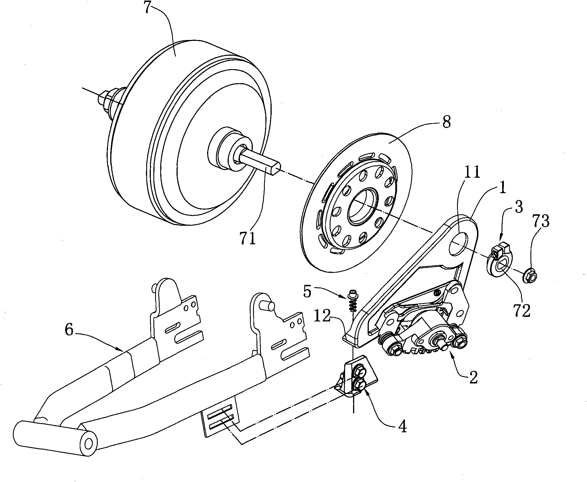
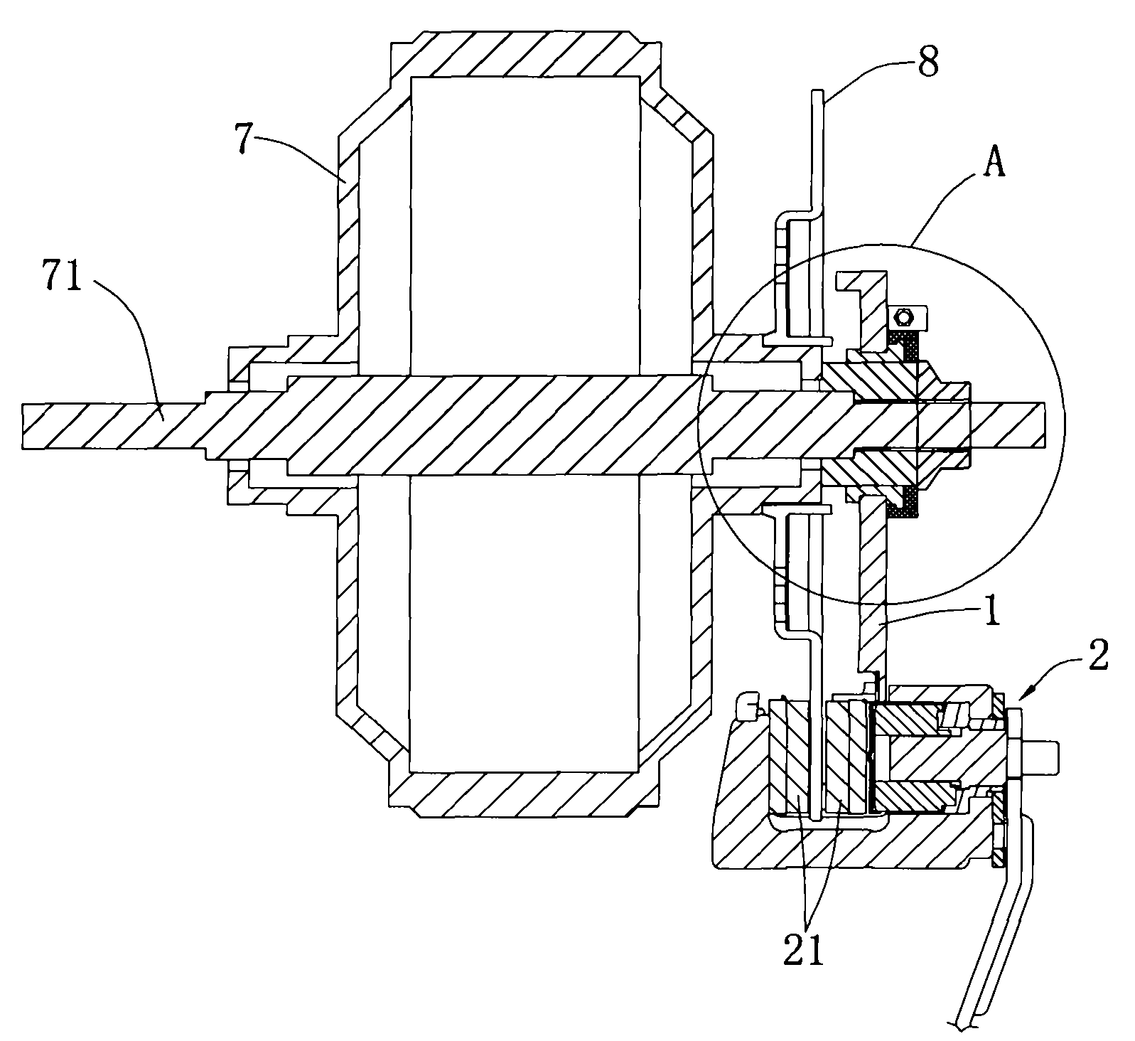
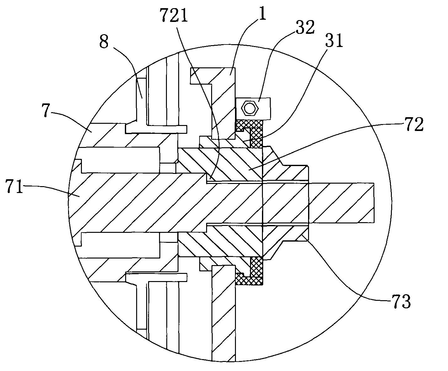
[0019] Such as figure 1 As shown, the present invention is an improved installation structure of an electric vehicle disc brake, which includes a disc brake assembly 2 and a mounting plate 1 for fixing the disc brake assembly 2. The mounting plate 1 is provided with a first mounting plate for connecting the wheel shaft 71. A mounting part and a second mounting part for connecting the vehicle frame 6, the wheel shaft 71 is provided with a disc 8, and the wheel shaft 71 is also provided with a positioning mechanism concentrically installed with the wheel shaft 71, and the mounting plate 1 passes through The first connecting mechanism 3 provided on the first mounting part is locked on the positioning mechanism, and the second mounting part is connected to the vehicle frame 6 through the second connecting mechanism 4, and the second connecting mechanism 4 and the second The installation part is a rotary connection.
[0020] refer to figure 2 , image 3 , Figure 4 , a preferr...
PUM
 Abstract
Description
Claims
Application Information