Sealed small low-impact release screw bolt

A technology of unlocking bolts and low impact is applied in the field of pyrotechnic connection and separation devices, which can solve the problems of weak sealing, large separation impact, unsatisfactory structural size and bearing capacity, etc., and achieves low impact, strong connection and good application prospects. Effect

Inactive Publication Date: 2010-11-03
BEIJING INSTITUTE OF TECHNOLOGYGY
0 Cites 41 Cited by

AI-Extracted Technical Summary

Problems solved by technology

For the existing pyrotechnic connection and separation device, on the one hand, the structural size and bearing capaci...

Method used

(1) select the higher material of intensity, preliminarily design out a kind of pyrotechnic unlocking bolt separation device; Under the premise that guarantees the connection strength of single device more than 12kN, based on optimization design idea, by the Matlab program of self-compilation to each The size and number of parts are gradually optimized. According to the optimization results, three metal wedges distributed in the circumferential direction of 1200 are finally used as the connection mechanism between the outer cylinder and the inner cylinder, so that after the device is fully assembled, the total length is 52.5mm (excluding the electric initiator), and the maximum outer diameter is 16mm. Device miniaturization. (2) By embedding a double O-ring sealing baffle inside the device, before the device of the present invention is separated, the piston and the double O-ring sealing baffle contact and cooperate; after separation, the piston is separated from the outer cylinder, and the double O-ring sealing baffle It is stuck inside the outer cyl...

Abstract

The invention relates to a sealed small low-impact release screw bolt. The bolt comprises an inner cylinder (1), a shear pin (2), a wedge block (3), a piston (4), a sealing ring (5), a double O-shaped ring sealed baffle (6) and an outer cylinder (7). The bolt is characterized by small size, sealing type, low impact, strong connection and no pollution. Before separated, the two polars of the connected body form strong connection; and when separated, the two polars of the connected body can be safely and fast separated and generate low impact disturbance, thus the bolt is a pyrotechnic connection separating device with good comprehensive performance, and can be directly used in the stage separating systems of the missile and other spacecrafts, also provide beneficial reference for the design of the similar separating mechanism, have good application prospect.

Application Domain

Cosmonautic component separation

Technology Topic

Image

  • Sealed small low-impact release screw bolt
  • Sealed small low-impact release screw bolt
  • Sealed small low-impact release screw bolt

Examples

  • Experimental program(1)

Example Embodiment

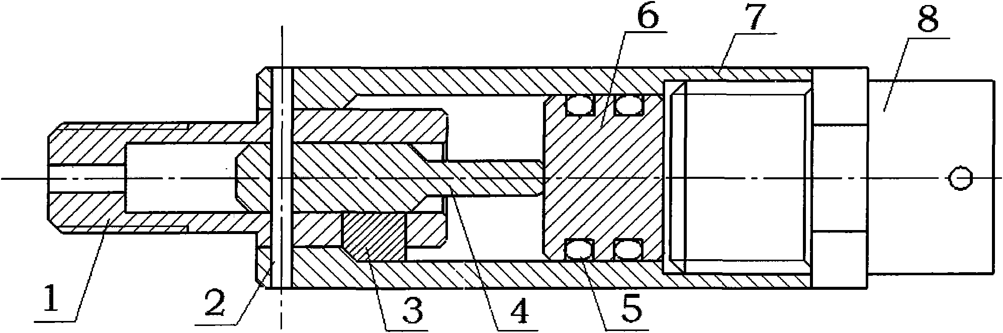
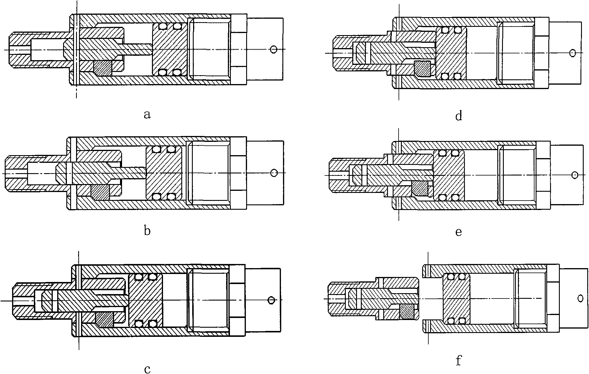
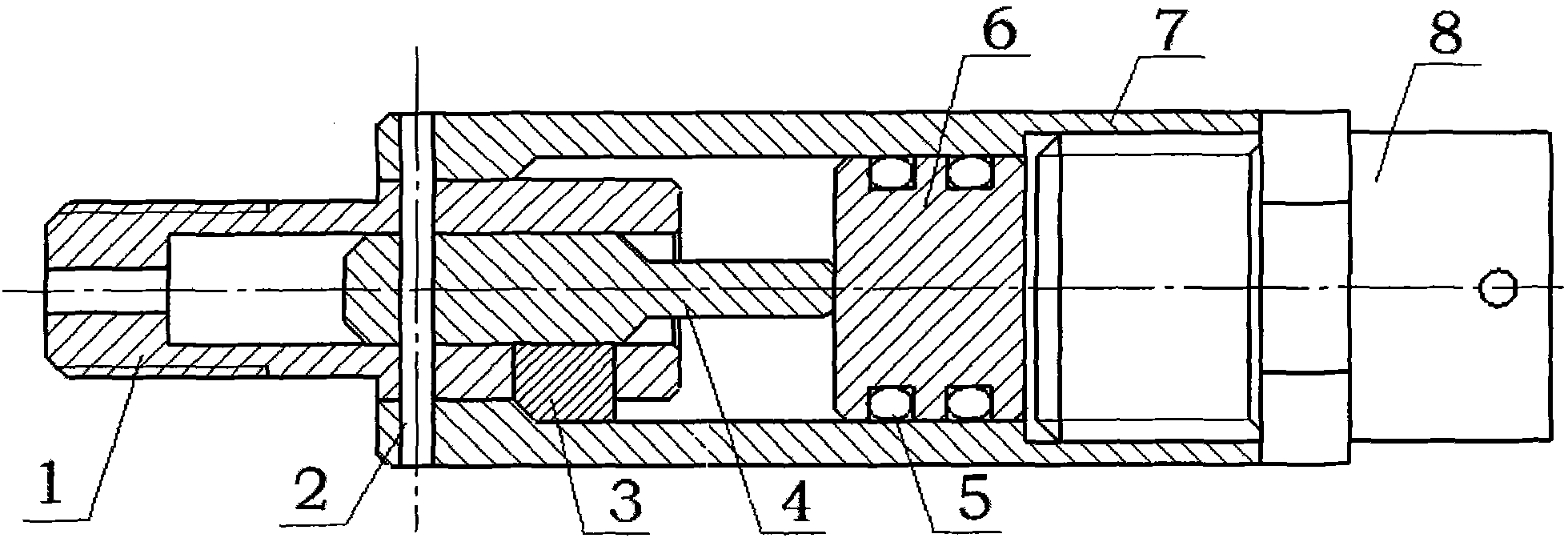
[0012] (1) Select high-strength materials, and initially design a pyrotechnic unlocking bolt separation device; under the premise of ensuring the connection strength of a single device is more than 12kN, based on the optimization design idea, the Matlab program compiled by ourselves is used to determine the size of each component. and the number to be gradually optimized. According to the optimization results, three metal wedges distributed in the circumferential direction of 1200 are used as the connection mechanism between the outer cylinder and the inner cylinder. Miniaturization of the device. (2) By embedding the double O-ring sealing baffle in the device, before the device of the present invention is separated, the piston and the double O-ring sealing baffle contact and cooperate; after separation, the piston is separated from the outer cylinder, and the double O-ring sealing baffle Being stuck inside the outer cylinder, the driving gas generated by the electric detonator is prevented from leaking out, and the high sealing performance and no pollution of the device are realized. (3) The outer cylinder, the inner cylinder and the piston are fixed by shear pins to prevent random rotation of the internal mechanism of the device and ensure the fixation and stability of the device cooperation. (4) Based on the idea of ​​"strong connection and weak unlocking", a metal wedge with high tensile strength is used as the connection locking structure before the device of the present invention is separated. Strong connection. (5) The shear pin is used as the pre-tightening mechanism during separation, and the unlocking separation is realized by shearing the shear pin twice in succession by the piston and the inner cylinder, which greatly reduces the power required for separation, and makes the impact disturbance during separation at Below 2N·s, weak unlocking and low impact are achieved.
[0013] exist figure 1 In the inner cylinder (1), one end of the inner cylinder (1) is threadedly connected with the connecting module of the missile or spacecraft, and the other end is positioned and installed with the piston (4) through a short positioning pin; three wedges (3) are installed in a circumferential direction of 120°. Put them into the three holes reserved in the inner cylinder (1), and put them into the outer cylinder (7) together. Use the shear pin (2) to push out the positioning pin, and insert the outer cylinder (7), the inner cylinder (1) and the piston into the outer cylinder (1). (4) A fixed assembly is formed between the three; install two sealing rings (5) on the double O-ring sealing baffle (6), and put them into the outer cylinder (7) together until they are connected with the thin end of the piston (4). Finally, the electric detonator (8) is installed on the end of the outer cylinder (7) through screw fitting, and the front end of the outer cylinder (7) is aligned with the missile or spacecraft connecting compartment to form a connection.
[0014] figure 2 The 6 pictures in the order of a-b-c-d-e-f show the working principle of the present invention: before separation, the inner cylinder (2) is threadedly connected with the missile or spacecraft connecting cabin, and the outer cylinder (7) is aligned with the connecting cabin. Installed to form the initial state (a) of the connection between the two stages of the separation body; during separation, the detonator (8) generates high-temperature and high-pressure gas expansion after detonation to do work, pushes the piston (4) to move, shears the shear pin for the first time, and reaches the state ( b); The piston (4) continues to move. When the groove of the piston (4) and the wedge (3) are facing each other, the wedge (3) begins to fall to In the groove of the piston (4), the state (c) is reached; the wedge (3) and the piston (4) continue to advance under the push of the double O-ring sealing baffle (6) until the double O-ring sealing baffle (6) Push the inner cylinder (1) to cut the shear pin for the second time to reach state (d); with the complete shearing of the shear pin (2) and the complete drop of the wedge (3), the inner cylinder begins to quickly separate from the outer cylinder The cylinder reaches state (e); finally, the inner cylinder (1) carries the piston (4) and is completely separated from the outer cylinder (7) together with the falling three wedges (3), and reaches state (f).

PUM

no PUM

Description & Claims & Application Information

We can also present the details of the Description, Claims and Application information to help users get a comprehensive understanding of the technical details of the patent, such as background art, summary of invention, brief description of drawings, description of embodiments, and other original content. On the other hand, users can also determine the specific scope of protection of the technology through the list of claims; as well as understand the changes in the life cycle of the technology with the presentation of the patent timeline. Login to view more.

Similar technology patents

Wheelchair suspension system

InactiveUS20100123296A1Reduce shockReduce vibrationWheelchairs/patient conveyanceConvertible cyclesCamber angleEngineering
Owner:CHELGREN ERIC MARK

80km/h speed class b-type subway vehicle bogie

ActiveCN101857033AReduce unsprung massReduce shockBogiesBogie-underframe connectionsAutomotive engineeringBrake force
Owner:ZHUZHOU ELECTRIC LOCOMOTIVE CO

Classification and recommendation of technical efficacy words

  • Strong connection
  • Reduce shock

Ball-and-socket joint

InactiveUS20060182491A1Strong connectionGood lockCouplings for rigid shaftsBellowsEngineeringBall and socket joint
Owner:TRW AUTOMOTIVE GMBH

Cellular heterogeneous network resource allocation method based on game theory

InactiveCN107864512ASatisfy traffic demandStrong connectionPower managementResource assignmentDynamic resource
Owner:NANJING UNIV OF POSTS & TELECOMM

Method for realizing fast coal exposing of coal seam rock cross with outburst danger

InactiveCN101598030AReduce shockBuffer and isolate the impactGas removalCoalPetrology
Owner:CHINA UNIV OF MINING & TECH

Crystal-chip polishing method

InactiveCN101069958AReduce shockPrecise pressure controlPolishing machinesSelf checkingLong axis
Owner:ZHEJIANG UNIV OF TECH
Why Eureka
Try Eureka