Method for identifying sensors on a bus by a control unit, as well as a control unit and a sensor for doing this

A sensor and controller technology, applied in the field of sensors, can solve problems such as expensive wiring, achieve the effect of simple cost, avoid blocking problems or conflict problems

Active Publication Date: 2010-11-03
ROBERT BOSCH GMBH
View PDF7 Cites 5 Cited by
  • Summary
  • Abstract
  • Description
  • Claims
  • Application Information

AI Technical Summary

Problems solved by technology

In principle, it is possible to define a sequence on the bus topology (first sensor in the bus, second sensor, ...), but such a daisy chain configuration would lead to exactly what should be avoided by the bus system expensive wiring

Method used


Image

  • Method for identifying sensors on a bus by a control unit, as well as a control unit and a sensor for doing this
  • Method for identifying sensors on a bus by a control unit, as well as a control unit and a sensor for doing this
  • Method for identifying sensors on a bus by a control unit, as well as a control unit and a sensor for doing this

Examples


Embodiment Construction

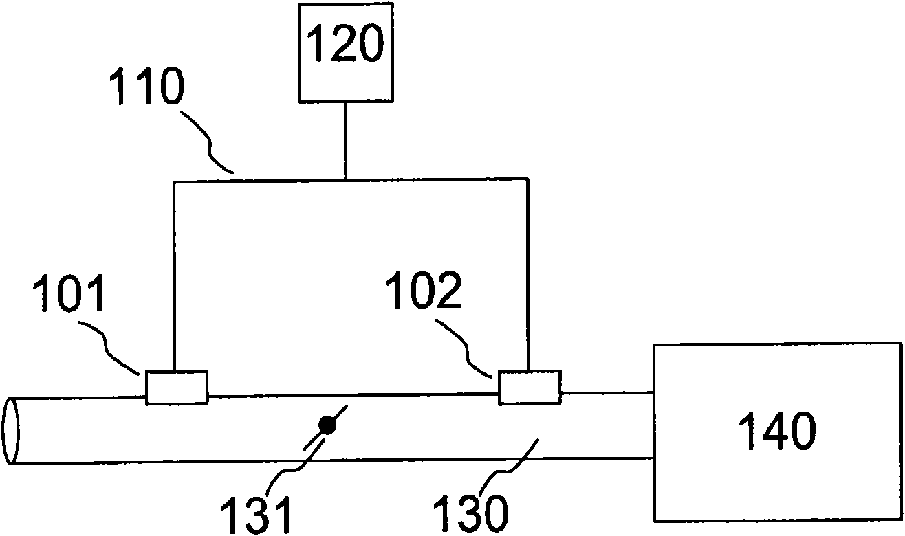
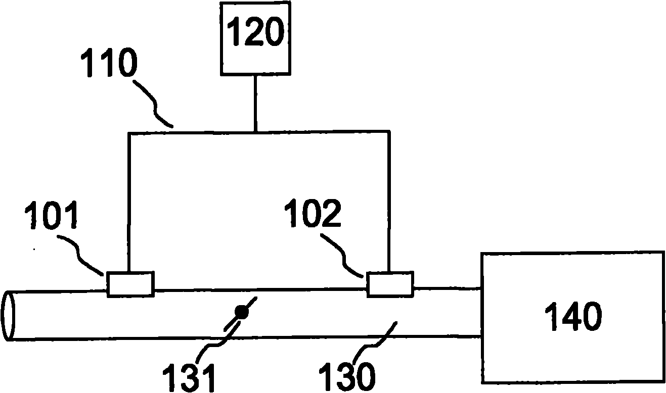
[0016] figure 1 An exemplary embodiment of the method according to the invention is shown on the basis of a pressure sensor at the intake manifold of an internal combustion engine with a turbocharger. In this case, two identically constructed pressure sensors 101 and 102 are used, which are connected via a star bus 110 to a controller 120 . Pressure sensors 101 and 102 are used on the intake pipe 130 , wherein the pressure sensor 101 is located before the throttle valve 131 of the intake pipe 130 , and the pressure sensor 102 is located between the throttle valve 131 and the internal combustion engine 140 . Therefore, the pressure sensor 101 measures the pressure before the throttle valve 131 (intake pressure), and the pressure sensor 102 measures the pressure between the throttle valve 131 and the internal combustion engine 140 (intake pipe pressure). These measured pressure data are communicated by pressure sensors 101 and 102 via bus 110 to controller 120 , wherein control...


PUM


Abstract

The invention relates to a method for identifying sensors on a bus by a control unit, as well as a control unit and a sensor for doing this. The sensors, in this instance, send physical useful data to the control unit as the basis for the control of a function. Furthermore, the physical useful data are compared to one another and / or to specified expected values, and the identification of the sensors by the control unit takes place with the aid of the comparison and based on characteristic differences in the physical useful data for the sensors.

Description

technical field [0001] The invention relates to a method for identifying a sensor on a bus by a controller, a controller and a sensor. Background technique [0002] So far, the application of bus systems for connecting sensors in automobiles is still quite rare. However, such systems will be increasingly used in the future due to the numerous advantages they offer. In order to be able to use a sensor in such a system, it must be able to be unambiguously identified, otherwise the controller will not be able to distinguish which signal is from which sensor. In principle, it is possible to define a sequence on the bus topology (first sensor in the bus, second sensor, ...), but such a daisy chain configuration would lead to exactly what should be avoided by the bus system Expensive wiring. Therefore, favorable star topology is not feasible. In the case of multiple sensors of the same structure or of the same type on the bus, logically (Poka Yoke) or technically (wiring) solu...

Claims


Application Information

Patent Timeline
Patent Type & Authority Applications(China)
IPC IPC(8): G05B19/04F02D41/00F01N11/00
CPCG01D1/00G01D15/00
Inventor E·赖伦A·格罗斯曼B·奥皮茨J·格拉比斯M·罗森兰
Owner ROBERT BOSCH GMBH
Why Eureka
Try Eureka