Paint booth arrangement and method for directing airflow

Active Publication Date: 2010-02-23
GLOBAL FINISHING SOLUTIONS
View PDF11 Cites 29 Cited by
  • Summary
  • Abstract
  • Description
  • Claims
  • Application Information

AI Technical Summary

Benefits of technology

[0022]Since the air handlers are located at some height above the floor, means for supporting the units must be provided. Taking advantage of the high degree of structural strength already available in the twin exhaust and intake chambers of the present invention, the rearward sections of the air handling units are supported from underneath by intake and exhaust chambers. This support function of the air intake/exhaust assemblies provides a significant advantage when energy recovery system(s) are incorporated since most of the weight of an air handling unit so equipped is in the energy recovery device.
[0023]The front or forward sections of the air handling units are supported by hanging the units from structural steel beams. These beams are necessary in any case to hold the panels of the paint booth in place. Using them for the additional task of holding up the front of the air handlers accomplishes the unit support function with a small additional cost for heavier steel.
[0024]The low roof mounting of the ai

Problems solved by technology

If the air handler is located remotely from the paint booth, these ducts can be very large.
It is further noted that the placement of the heat exchanger in remote locations typically in the r

Method used


Image

  • Paint booth arrangement and method for directing airflow
  • Paint booth arrangement and method for directing airflow
  • Paint booth arrangement and method for directing airflow

Examples


Example

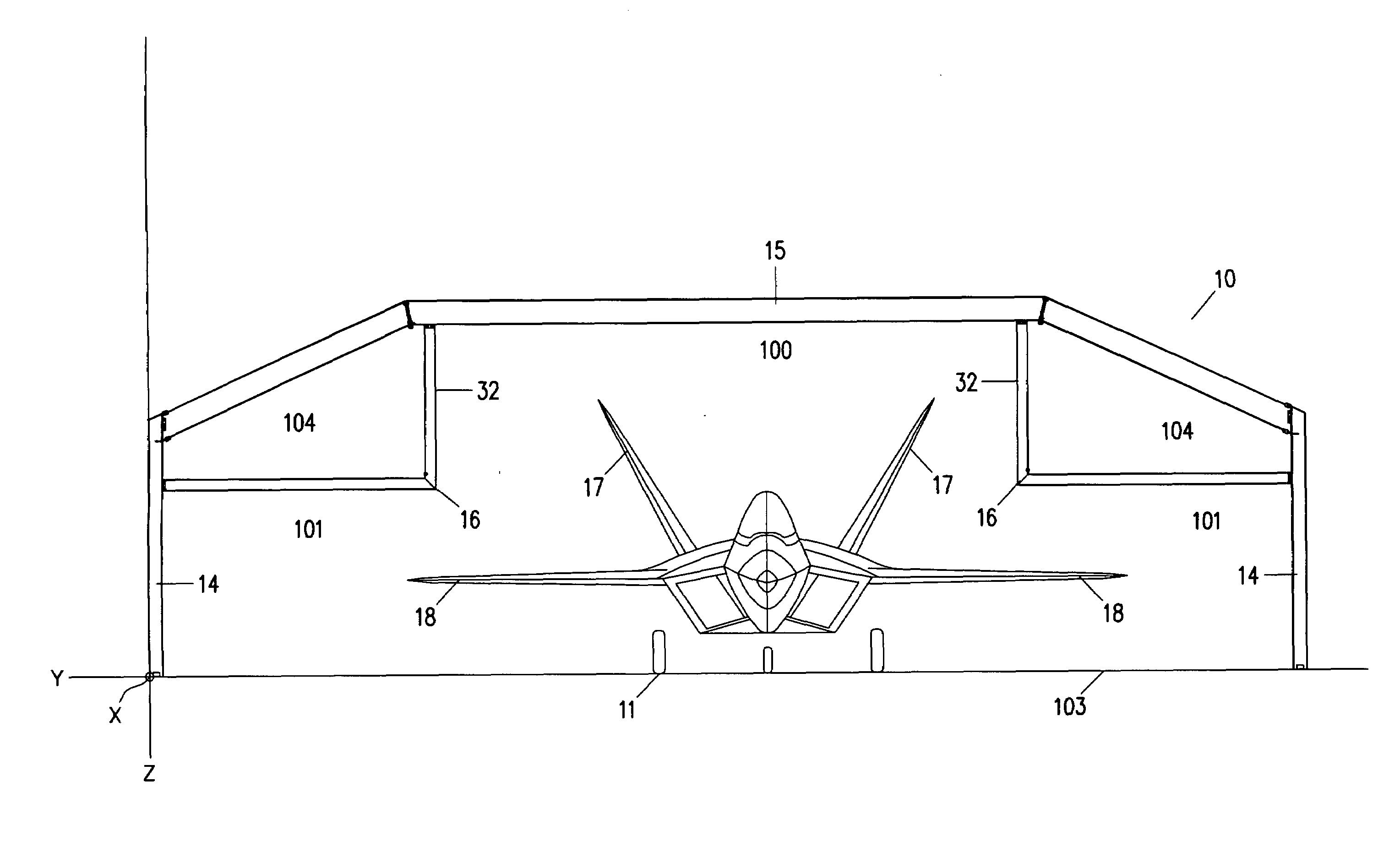
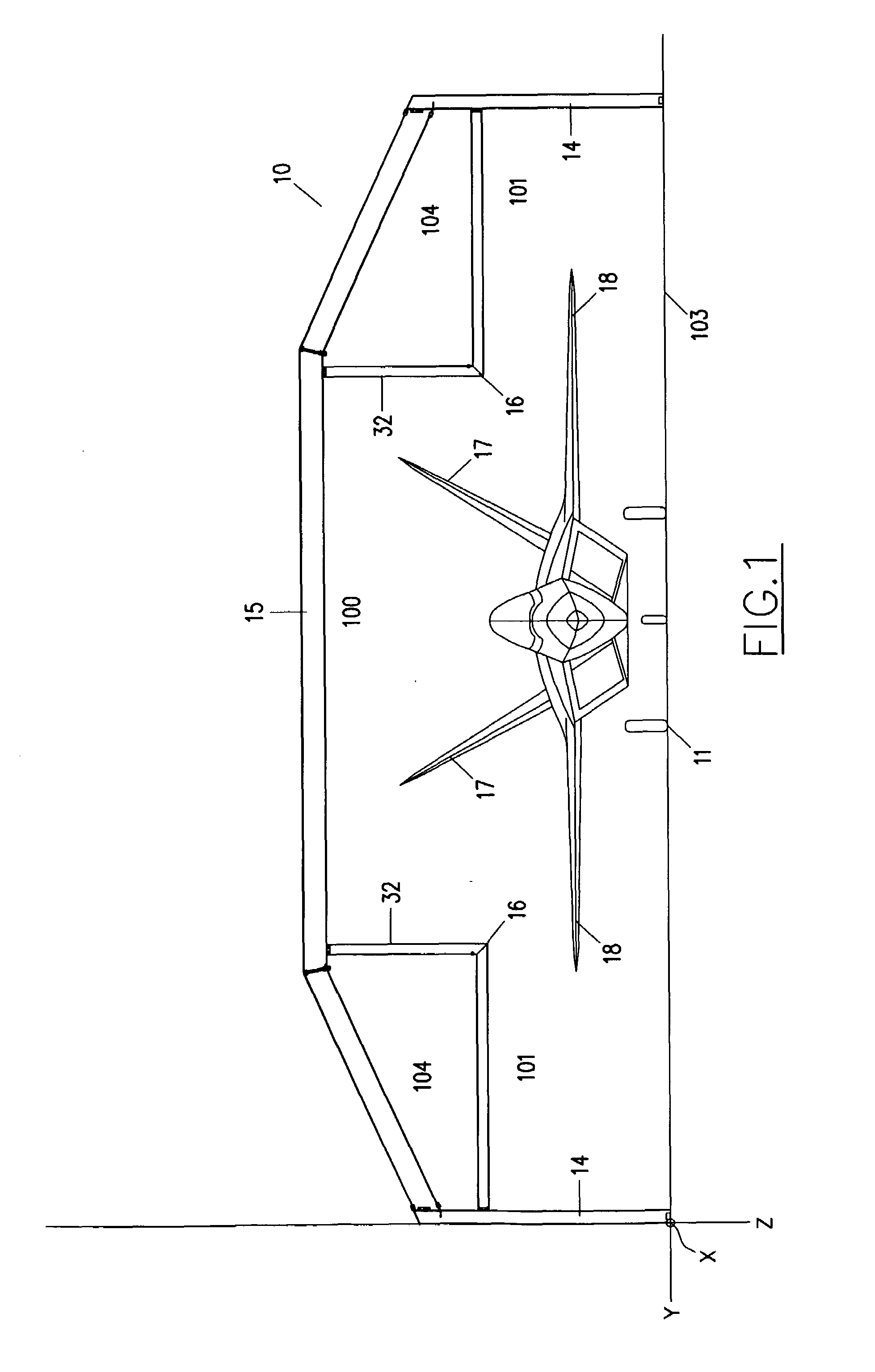
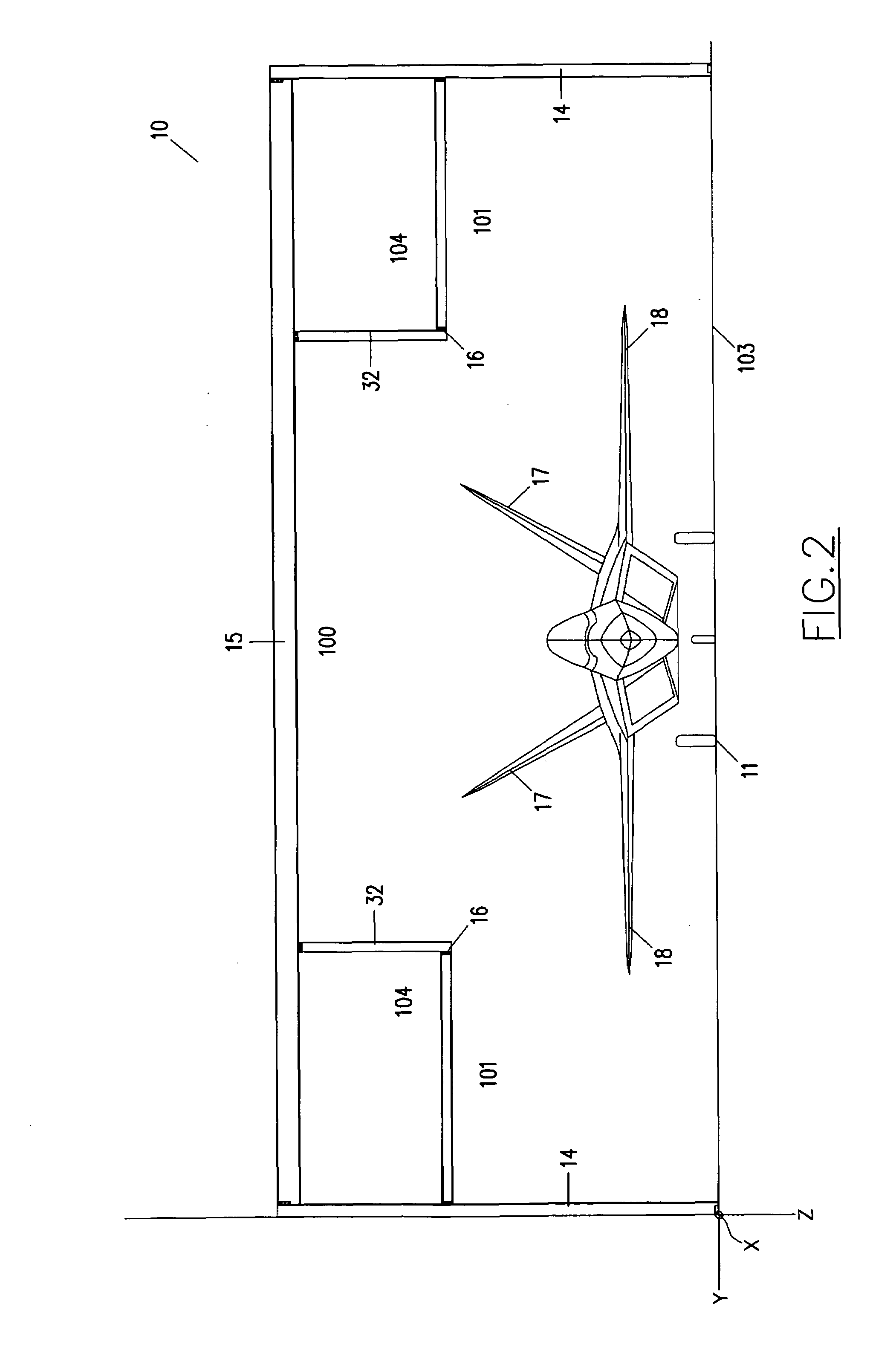
[0051]Referring now to the drawings with more specificity, the preferred embodiment of the present invention concerns a paint booth structure and / or arrangement 10 specifically designed to maximize available floor space as well as overall efficiency of a painting operation. Although the paint booth arrangement or structure 10 according to the present invention is designed primarily for enclosing and enabling painting operations tailored for low observable aircraft, it is believed that the principles underlying the arrangement of the structure 10 may well be applied to any number of paint booth scenarios or situations in which paintable equipment are booth-received in order to be provided with protective coatings and the like. In other words, it is contemplated that other paintable equipment such as aircraft in general, land craft, and / or spacecraft may well benefit from the principles hereafter specified. Certain exemplary aircraft 11 are generally depicted and referenced in FIGS. 1...


PUM


Abstract

A paint booth arrangement maximizes floor space and efficiency of a painting operation. The arrangement comprises an equipment enclosing structure and certain air handling equipment specifically configured within the structure. The structure comprises forward and rearward sections, opposed wall sections, a centralized roof section, and opposed wall-to-roof sections, which sections define open space having varied elevation for receiving paintable equipment. The air handling equipment comprises an air intake and exhaust assemblies and an air replacement system. The air intake and exhaust assemblies extend coextensively intermediate the wall sections at the rearward section and function to support portions of the air replacement system. The air replacement system comprises conduit extending intermediate the forward and rearward sections as defined by the wall-to-roof sections. The air intake assembly communicates with the conduit for directing inlet airflow to the open space, and the air exhaust assembly comprises exhausts airflow from the open space.

Description

BACKGROUND OF THE INVENTION[0001]1. Field of the Invention[0002]The present invention generally relates to a paint booth construction. More particularly, the present invention relates to a paint booth arrangement and method for directing airflow through the paint booth for maximizing floor space and operational efficiency.[0003]2. Brief Description of the Prior Art[0004]Paint booths are used to enclose certain dangerous activities that are performed therein (such as painting and stripping) and to contain the risk of fire. Paint booths are further utilized to control the overspray from the spray paint guns and capture the paint particles that are not applied to the object being painted. Paint booths are designed in accordance with local and national electrical and fire codes and are usually surrounded with single or double skinned walls. Some of the more pertinent prior art relating to paint / spray booths and the like are briefly described hereinafter.[0005]U.S. Pat. No. 4,515,072 ('0...

Claims


Application Information

Patent Timeline
IPC IPC(8): B05B15/12
CPCB05B15/1222B05B16/60
Inventor THELEN, RICHARD L.
Owner GLOBAL FINISHING SOLUTIONS
Why Eureka
Try Eureka