Magnetic resistance type magnetic suspension device

A suspension device and magnetoresistive technology, applied in the field of magnetic suspension, can solve the problems of high cost, low energy consumption and high energy consumption of the magnetic suspension device, and achieve the effect of large magnetic force and low energy consumption

Inactive Publication Date: 2010-11-03
HENAN POLYTECHNIC UNIV
View PDF0 Cites 10 Cited by
  • Summary
  • Abstract
  • Description
  • Claims
  • Application Information

AI Technical Summary

Problems solved by technology

[0004] The present invention aims to solve the problems of high energy consumption and high cost in the magnetic levitation device, and provides a reluctance type magnetic levitation device with low energy consumption, low cost, and at least an order of magnitude greater than the restoring force of ordinary magnets

Method used


Image

  • Magnetic resistance type magnetic suspension device
  • Magnetic resistance type magnetic suspension device
  • Magnetic resistance type magnetic suspension device

Examples


Embodiment 1

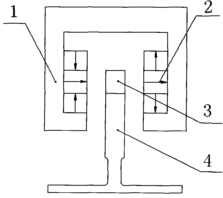
[0043] figure 1 Among them, the magnetoresistive magnetic levitation device includes a magnet frame 1, two rows of magnet arrays 2 arranged in the form of Halbach arrays are fixed on both sides of the non-magnetically conductive magnet frame 1, and the two rows of Halbach arrays 2 are arranged in parallel and at equal heights, and each row of Halbach arrays Array 2 contains three magnets, and the magnetization directions of the three magnets from top to bottom in one column are as follows: vertically upward, horizontally to the right, and vertically downward; corresponding to the magnetization of the other three magnets from top to bottom The directions are as follows: vertically downward, horizontally to the right, and vertically upward, a loop of magnetic force lines is formed between two rows of Halbach arrays 2; between the two rows of Halbach arrays 2 is a magnetically conductive yoke I3, and the yoke I3 and the Halbach arrays on both sides The air gaps of 2 are equal, an...

Embodiment 2

[0049] like Image 6 As shown, the yoke II 8 is fixed at the bottom of the Halbach array 2 , the yoke III 9 is fixed between the Halbach array 2 and the magnet frame 1 , and other structures are the same as in the first embodiment.

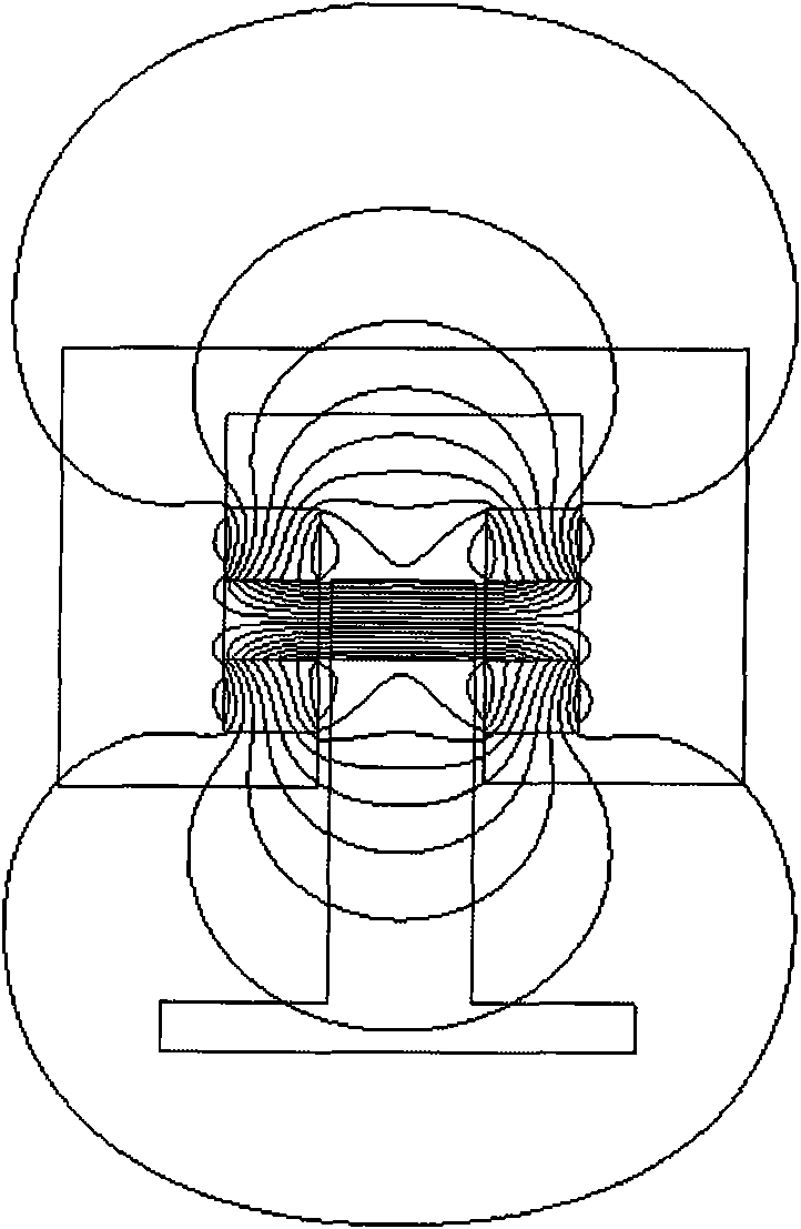
[0050] like Figure 7 As shown, after the upper and lower ends of the two Halbach arrays 2 are respectively fixed with yokes II8 and III9, the schematic diagram of the distribution of magnetic force lines between the two Halbach arrays 2 is shown. The magnetic field path at the center of the two Halbach arrays 2 is the shortest, and the magnetic field path at the upper and lower ends is the longest. From the principle of Embodiment 1, it can be seen that when the horizontal centerline of the yoke I3 coincides with the centerline of the middle magnet in the Halbach array 2, the vertical force on the yoke I3 is minimal. When the yoke I3 moves upward, the yoke I3 is subjected to the downward restoring force of the magnet; on the contrary, when the yo...

Embodiment 3

[0053] like Figure 11 As shown, two rows of magnet arrays 11 arranged at intervals are fixed on both sides of the magnet frame 1, and a magnetic field line loop is formed between the two rows of interval arrays 11. A magnet, a protruding iron 10 is set between the two magnets; the magnetization directions of the two magnets are vertical and the magnetization directions are opposite, and in the two spaced arrays 11, the magnetization directions of the two magnets in parallel positions are opposite; the two spaced arrays Between 11 is a magnetically conductive yoke I3, the air gap between the yoke I3 and the spaced arrays 11 on both sides is equal, and the yoke I3 is supported by a non-magnetically conductive yoke frame 4.

[0054] like Figure 12 Shown is a schematic diagram of the distribution of magnetic force lines between two spaced arrays 11 . The magnetic field path at the center of the two spacing arrays 11 is the shortest, and the magnetic field path at the upper and...


PUM


Abstract

The invention discloses a magnetic resistance type magnetic suspension device which relates to the field of magnetic suspension. The magnetic resistance type magnetic suspension device comprises a magnet bracket, wherein two magnet arrays are respectively fixed in the magnet bracket in opposite directions; a yoke is arranged between the two magnet arrays; the two magnet arrays are respectively fixed at both sides in the nonmagnetic-conduction magnet bracket; a magnetic force line loop is formed between the two magnet arrays; a yoke I is arranged between the two arrays; the yoke I is equal to the air gaps of the arrays at the two sides; and the yoke I is supported by the nonmagnetic-conduction magnet bracket. In the magnetic resistance type magnetic suspension device, the permanent magnets are arranged based on a certain form, thereby having large magnetic force; and the magnetic suspension device can work at ordinary temperature and does not need power supply in operation, thereby consuming little energy.

Description

technical field [0001] The invention belongs to the field of magnetic levitation, and in particular relates to a reluctance type magnetic force levitation device. Background technique [0002] Magnetic levitation technology has very important potential applications in scientific research, industry, transportation and other fields. At present, the common levitation mechanisms include: constant conductive electromagnetic levitation, superconducting electromagnetic levitation and ordinary permanent magnetic levitation. Ordinary conductive magnetic levitation devices need power consumption, complex control technology, and high energy consumption; superconducting electromagnetic levitation devices need to provide ultra-low temperature environments, high energy consumption, and high cost; ordinary permanent magnetic levitation is homopolar repulsive magnetic levitation, its recovery force is small, and the cost is high , complex layout, and large amount of construction work. [0...

Claims


Application Information

Patent Timeline
Patent Type & Authority Applications(China)
IPC IPC(8): H02N15/00
Inventor 汪旭东许孝卓杜宝玉司纪凯上官璇峰封海潮袁世鹰王旭强
Owner HENAN POLYTECHNIC UNIV
Why Eureka
Try Eureka