Needle guiding support device

A support device and needle body technology, applied in the direction of puncture needles, trocars, medical science, etc., can solve the problems of adjusting the angle of the needle insertion plane, the inability to use the guide instrument, and inaccurate needle insertion, so as to reduce the amount of radiation and shorten the Less operation time and less cost

Inactive Publication Date: 2010-11-10
张惠玲 +1
View PDF3 Cites 16 Cited by
  • Summary
  • Abstract
  • Description
  • Claims
  • Application Information

AI Technical Summary

Problems solved by technology

Although the devices are simple in structure and can be used by hand, there is no setting to ensure that the actual needle entry level of the puncture needle completely coincides with the scanning level where the lesion is located and to ensure that the actual needle entry angle of the puncture needle is consistent with the needle entry angle required by CT. The alignment components with exactly the same angle, so the CT-guided puncture locator is only suitable for the zero-degree situation where the CT frame is perpendicular to the hospital bed, which is convenient to use, but lacks accuracy
In this way, when the scanning level where the lesion is located is obtained when the CT gantry is tilted at a certain angle, the doctor cannot use the guide instrument to adjust the angle of the needle insertion level, so that the doctor can only visually observe and make adjustments based on experience
In addition, this device is a guiding instrument independent of the puncture needle. Due to the influence of experience and some on-site factors, it is easy to cause inaccurate needle insertion. Sometimes it is necessary to repeat the needle insertion many times. The treatment has brought great inconvenience, but also brought great pain and risk to patients

Method used


Image

  • Needle guiding support device
  • Needle guiding support device
  • Needle guiding support device

Examples


Embodiment Construction

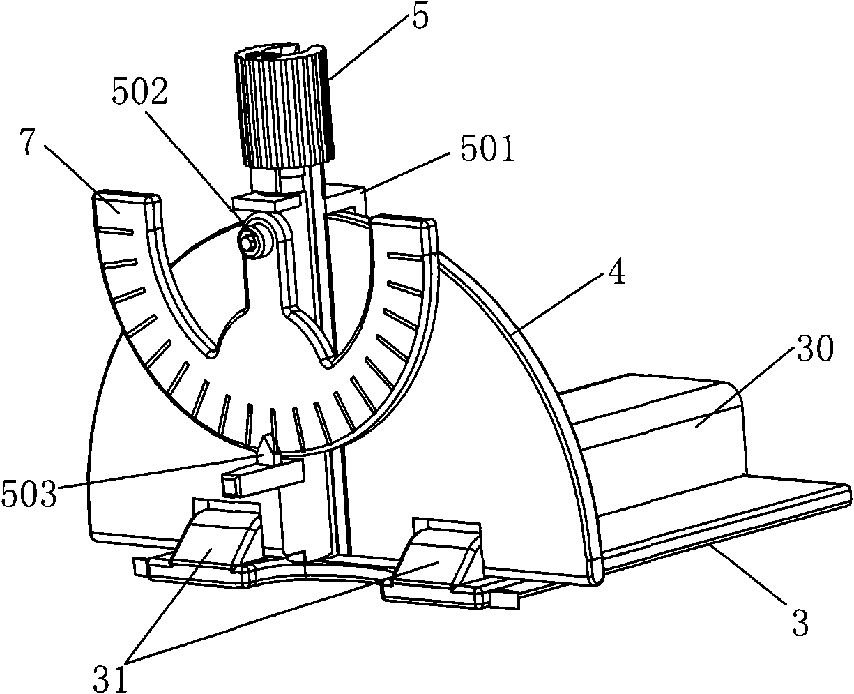
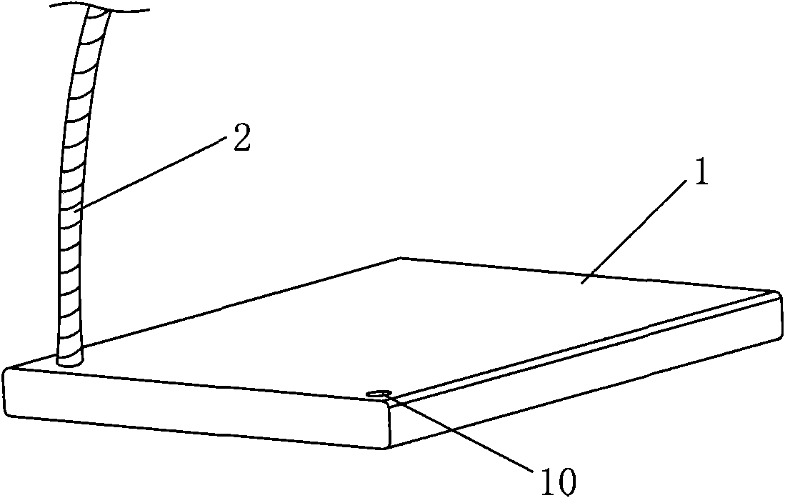
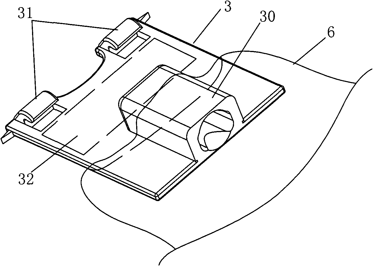
[0038] Such as Figure 1 to Figure 6 As shown, the needle guiding and supporting device according to the present invention is composed of a guiding and supporting structure and a direction indicating plate. The folded universal connecting rod 2, the connecting plate 3 connected with the universal connecting rod 2, the support plate 4 movably connected with the connecting plate 3, the puncture needle support 5 installed on the support plate 4 for fixing the puncture needle and guiding and the sheath 6 installed on the connecting plate 3 and set on the universal connecting rod, such as Figure 6 As shown, the direction indicating plate 7 is a semicircular instrument structure, installed on the puncture needle support 5, the plane where the direction indicating plate 7 is located is parallel to the straight line where the puncture needle is located, and the plane of the support plate 4, and the center of the circle 70 and the plane of the support plate 4 are parallel to each othe...


PUM


Abstract

The invention discloses a needle guiding support device, which consists of a guiding support structure and a direction indicating plate. The guiding support structure consists of a base, a universal connecting rod, a connecting plate, a supporting plate, a puncture needle supporting piece, and a sheath, wherein the universal connecting rod is connected with the base and can be bent in any direction; the connecting plate is connected with the universal connecting rod; the supporting plate is movably connected with the connecting plate; the puncture needle supporting piece is arranged on the supporting plate and is used for fixing a puncture needle and guiding; and the sheath is arranged on the connecting plate and sleeved on the universal connecting rod. The direction indicating plate has a graphometer structure and is arranged on the puncture needle supporting piece; a plane where the direction indicating plate is positioned is parallel to a line where the puncture needle is positioned; the center of the circle of the direction indicating plate is movably connected with the puncture needle supporting piece, so that the direction indicating plate can freely swing; an angle scale is marked on the circumference of the direction indicating plate; an indicating scale which corresponds to a symmetry axis is 0 degree, and is a centre-of-gravity position in a vertical plane; and the scale is uniformly arranged from 90 degrees below zero to 90 degrees on an arc on left and right sides of the zero-degree angle respectively. The needle guiding support device has the advantages of convenient operation, simple structure, and low cost.

Description

technical field [0001] The invention relates to a medical auxiliary device, in particular to a needle guiding and supporting device for puncture positioning. Background technique [0002] When a lesion occurs inside the human body, it is sometimes necessary to use a puncture to biopsy or treat the lesion. Usually, the orientation of the lesion and the skin location point and the depth of the puncture needle are measured by means of an instrument such as a CT scanning device. Angle, using the three-dimensional conformation of the needle entry level, needle entry angle, and needle entry depth to determine the precise location of the lesion and puncture needle. Although the CT scanning device can accurately determine the three-dimensional needle insertion angle and depth, the puncture process is performed after the patient is removed from the CT scanning layer. When the patient leaves the CT scanning device, the doctor can only use his own judgment , to determine a general ne...

Claims


Application Information

Patent Timeline
Patent Type & Authority Applications(China)
IPC IPC(8): A61B19/00A61B17/34
Inventor 张惠玲冯威健
Owner 张惠玲
Why Eureka
Try Eureka