Installation method of a coiled tubing defect spray marking system
A system installation and tubing technology, which is applied to printing devices, typewriters, printing, etc., can solve problems such as inability to accurately locate and affect the safety of tubing operations, and achieve the effects of ensuring operational safety, facilitating re-inspection and repairing, and reducing operating costs
- Summary
- Abstract
- Description
- Claims
- Application Information
AI Technical Summary
Problems solved by technology
Method used
Image
Examples
Embodiment 1
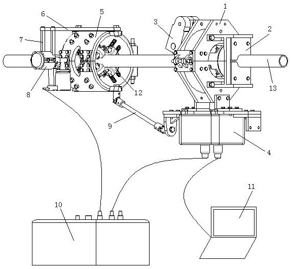
[0033] see figure 1 , a coiled tubing defect spray marking system installation method, comprising the following steps:
[0034] S1, install the coiled tubing 13 through the marking positioning device, and set the roller encoder 3 on the magnetic flux leakage detection unit 1 of the coiled tubing magnetic flux leakage detection device;
[0035] S2, then the marking positioning device is connected with the electric control box 10, the coiled tubing magnetic flux leakage detection device is connected with the signal processing box 4, and the signal processing box 4 is connected with the electric control box 10 and the computer 11 respectively;
[0036] S3. Finally, insert the debugged paint spray gun 8 into the spray gun ferrule 7, and align the nozzle of the paint spray gun 8 with the wall of the coiled tubing 13.
[0037] This embodiment is the most basic implementation mode, S1, install the coiled tubing 13 through the marking positioning device, set the roller encoder 3 on t...
Embodiment 2
[0039] seefigure 1 , a coiled tubing defect spray marking system installation method, comprising the following steps:
[0040] S1, install the coiled tubing 13 through the marking positioning device, and set the roller encoder 3 on the magnetic flux leakage detection unit 1 of the coiled tubing magnetic flux leakage detection device;
[0041] S2, then the marking positioning device is connected with the electric control box 10, the coiled tubing magnetic flux leakage detection device is connected with the signal processing box 4, and the signal processing box 4 is connected with the electric control box 10 and the computer 11 respectively;
[0042] S3. Finally, insert the debugged paint spray gun 8 into the spray gun ferrule 7, and align the nozzle of the paint spray gun 8 with the wall of the coiled tubing 13.
[0043] In the step S1, setting the coiled tubing 13 through the marking positioning device specifically refers to installing the coiled tubing 13 on the support base ...
Embodiment 3
[0046] see figure 1 , a coiled tubing defect spray marking system installation method, comprising the following steps:
[0047] S1, install the coiled tubing 13 through the marking positioning device, and set the roller encoder 3 on the magnetic flux leakage detection unit 1 of the coiled tubing magnetic flux leakage detection device;
[0048] S2, then the marking positioning device is connected with the electric control box 10, the coiled tubing magnetic flux leakage detection device is connected with the signal processing box 4, and the signal processing box 4 is connected with the electric control box 10 and the computer 11 respectively;
[0049] S3. Finally, insert the debugged paint spray gun 8 into the spray gun ferrule 7, and align the nozzle of the paint spray gun 8 with the wall of the coiled tubing 13.
[0050] In the step S1, setting the coiled tubing 13 through the marking positioning device specifically refers to installing the coiled tubing 13 on the support bas...
PUM
 Abstract
Description
Claims
Application Information
 - R&D
- Intellectual Property
- Life Sciences
- Materials
- Tech Scout
- Unparalleled Data Quality
- Higher Quality Content
- 60% Fewer Hallucinations
Browse by: Latest US Patents, China's latest patents, Technical Efficacy Thesaurus, Application Domain, Technology Topic, Popular Technical Reports.
© 2025 PatSnap. All rights reserved.Legal|Privacy policy|Modern Slavery Act Transparency Statement|Sitemap|About US| Contact US: help@patsnap.com

