Steam dryer

A dryer and steam technology, applied in the direction of drying solid materials, non-progressive dryers, drying, etc., to achieve the effect of improving filling degree, increasing contact area and reducing downtime

Active Publication Date: 2010-11-10
KUMERA
View PDF5 Cites 13 Cited by
  • Summary
  • Abstract
  • Description
  • Claims
  • Application Information

AI Technical Summary

Problems solved by technology

Another problem with the US6415527 drum stems from the combined structure of the steam distribution manifold and discharge end chamber

Method used


Image

  • Steam dryer
  • Steam dryer
  • Steam dryer

Examples


Embodiment Construction

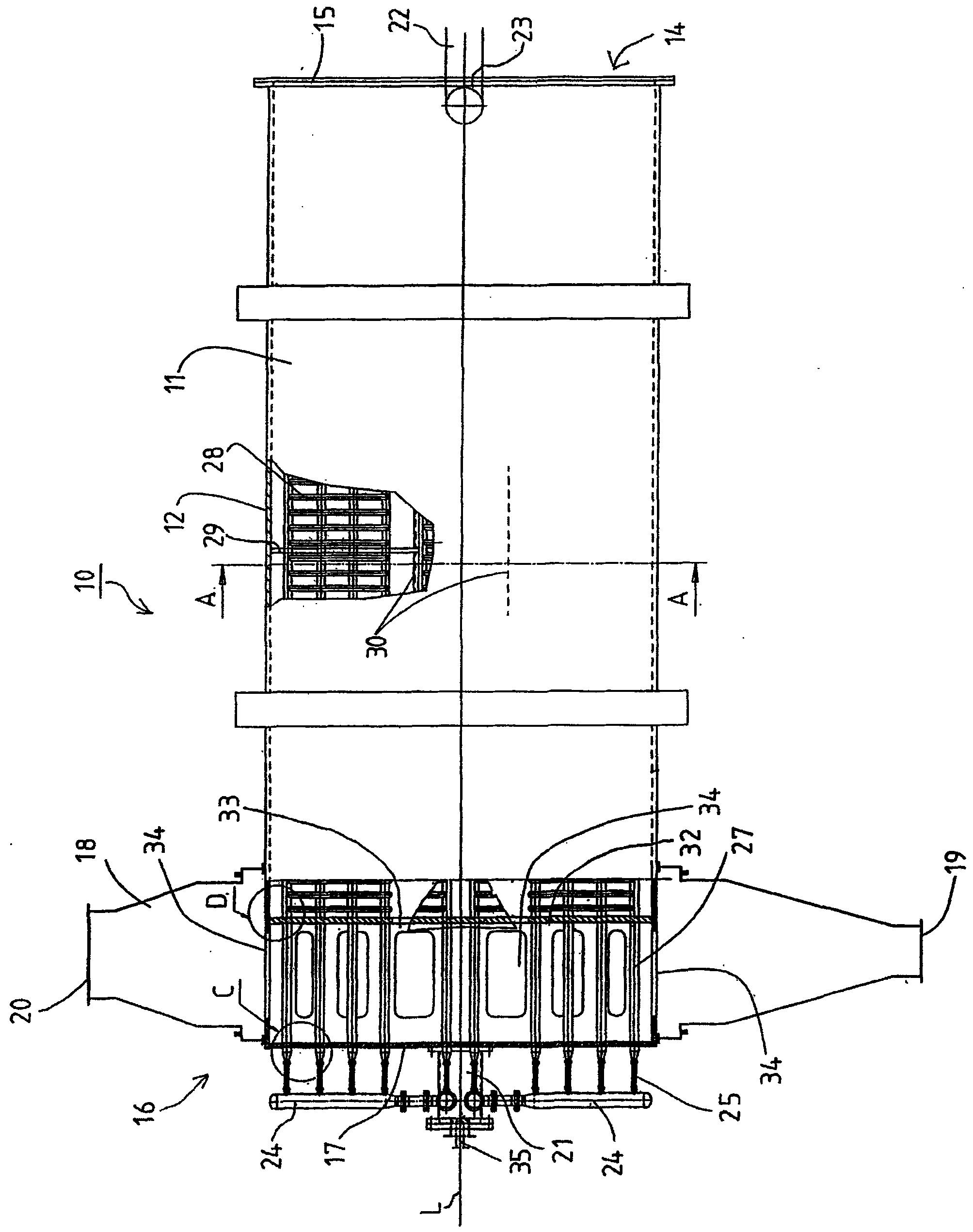
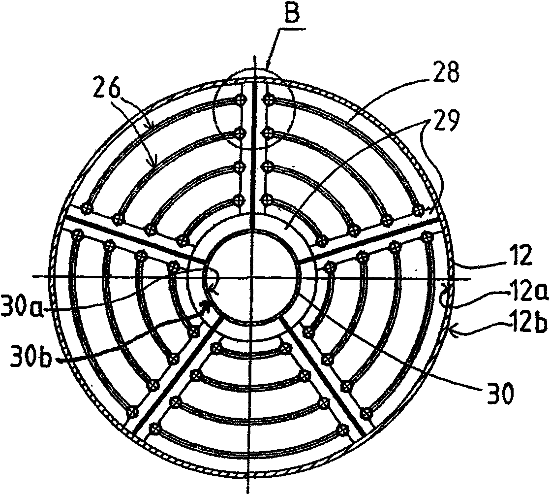
[0030] figure 1 A medium steam dryer is indicated generally by the reference numeral 10 . The steam dryer 10 comprises a cylindrical rotatable drum 11 having an outer shell 12 with an inner surface 12a and an outer surface 12b. The steam pipe member 26 is installed inside the drum 11 to rotate with the drum 11 . The drum 11 has a feed end 14 constructed and arranged to receive wet or liquid material into said drum 11 , the feed end 14 being defined by a feed end plate 15 . The drum 11 also has a discharge end 16 constructed and arranged to discharge off-gas and dry material or residual liquid from said drum 11 , the discharge end 16 being defined by a discharge end plate 17 .

[0031] The fixed end chamber 18 is configured and arranged axially between the discharge end plate 17 and the feed end plate 15 of the drum 11 in the area of ​​the discharge end 16 such that the discharge end plate 17 is located at the The outside of the discharge end chamber 18. Such as figure 1 Sai...


PUM


Abstract

The invention concerns a steam dryer for evaporating of water and/or other liquid from wet materials or evaporating of materials in a liquid state. The dryer comprises a cylindrical rotatable drum having a feed end and a discharge end; a plurality of steam pipe elements inserted in the drum, wherein each steam pipe element comprises axial pipes parallel to a longitudinal direction of the drum and interconnected by transverse intermediate pipes, and the steam pipe elements are rotatable with the drum; a stationary end chamber and a steam distributor manifold arranged at the discharge end area of the drum; conveyance means disposed at the feed end of the drum for supplying the wet materials or the materials in a liquid state into the steam dryer for evaporating. The stationary end chamber is arranged at the discharge end area of the drum in the axial direction between the discharge end plate and the feed end plate such that the discharge end plate is situated outside of the discharge end chamber. The discharge end chamber surrounds a portion of the drum and it has a lower opening to discharge dried material or remaining liquid and an upper opening to discharge vapour from the drum. The steam distributor manifold is arranged at the discharge end of the drum outside of the discharge end plate.

Description

technical field [0001] The invention relates to a steam dryer for evaporating water and / or other liquids in wet materials or evaporating liquid materials, comprising: [0002] A cylindrical rotatable drum having an outer shell having an inner surface and an outer surface, the drum having a feed end constructed and arranged to receive wet or liquid material into the drum and configured and arranged to receive wet or liquid material from the drum discharge end for exhaust gas and dry material or residual liquid, the feed end is defined by a feed end plate, the discharge end is equipped with a discharge end plate, [0003] a plurality of steam pipe elements, each steam pipe element comprising two axial pipes parallel to the longitudinal direction of the drum and interconnected by a plurality of longitudinally spaced transverse intermediate pipes, the steam pipe elements being constructed and arranged to be inserted into the interior of the drum , and rotate with it, [0004] a ...

Claims


Application Information

Patent Timeline
Patent Type & Authority Applications(China)
IPC IPC(8): F26B11/04F26B3/24F26B23/10
CPCF26B11/0409F26B11/026F26B11/045
Inventor 哈努·曼斯卡维塔陈绍隆
Owner KUMERA
Why Eureka
Try Eureka