Eureka AIR delivers breakthrough ideas for toughest innovation challenges, trusted by R&D personnel around the world.

Sealing device

A sealing device and external sealing technology, applied in the directions of engine sealing, transportation and packaging, shafts, etc., can solve the problems of decreased fuel consumption, difficulty in preventing the intrusion of mud and water, and inability to obtain the interference of casing 2, and achieve sliding rotation. The effect of small moment and excellent sealing performance against mud and water

Active Publication Date: 2010-11-10
NOK CORP
View PDF10 Cites 15 Cited by
  • Summary
  • Abstract
  • Description
  • Claims
  • Application Information

AI Technical Summary

Problems solved by technology

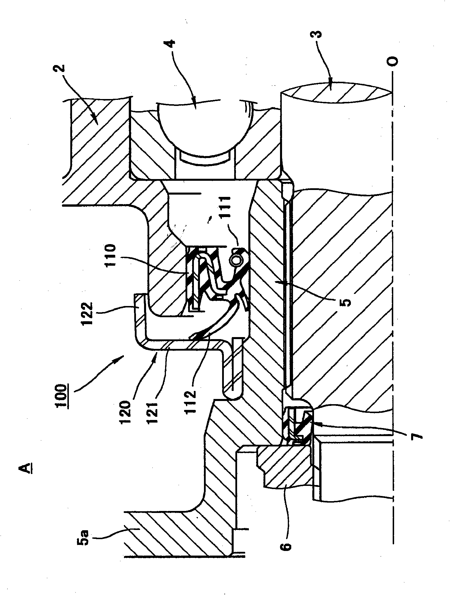
[0010] However, according to figure 2 In the sealing device 100 shown in (Patent Documents 1-3), if the gap between the outer cylindrical portion 122 of the flinger 120 and the outer peripheral surface of the end portion of the housing 2 is narrowed, problems such as machining tolerances or eccentricity of the rotating shaft 3 may occur. , the above-mentioned outer cylinder portion 122 may come into contact with the end peripheral surface of the housing 2, so the above-mentioned gap cannot be made small enough, so the intrusion of muddy water and the like cannot be sufficiently prevented.
[0011] In addition, as in Patent Document 4, the sealing device is provided with a conical cylindrical dustproof lip with a large diameter at the outer diameter end of the flinger 120, because the main body of the dustproof lip is in close contact with the opening end of the housing 2. Therefore, it is impossible to obtain a sufficient amount of interference to the housing 2, especially when walking on a bad road, when the sealing device is submerged in muddy water, it is difficult to prevent the intrusion of muddy water
In addition, in order to improve the muddy water sealing performance, it is also conceivable to increase the number of the side lip 112 and the dust lip. In this case, not only the sealing device 100 will be enlarged, but also the fuel may be caused by the increase of the sliding torque. Decrease in consumption rate

Method used


Image

  • Sealing device
  • Sealing device
  • Sealing device

Examples


Embodiment Construction

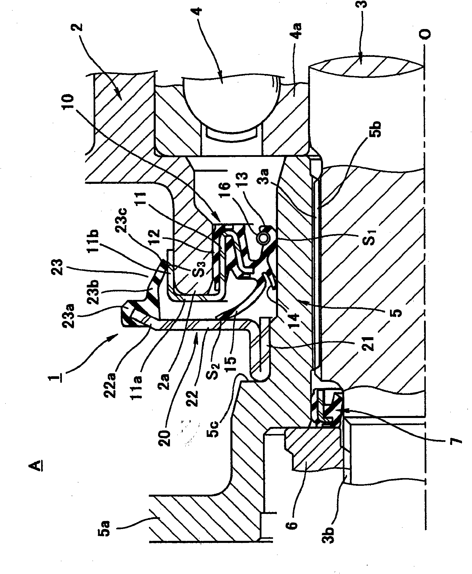
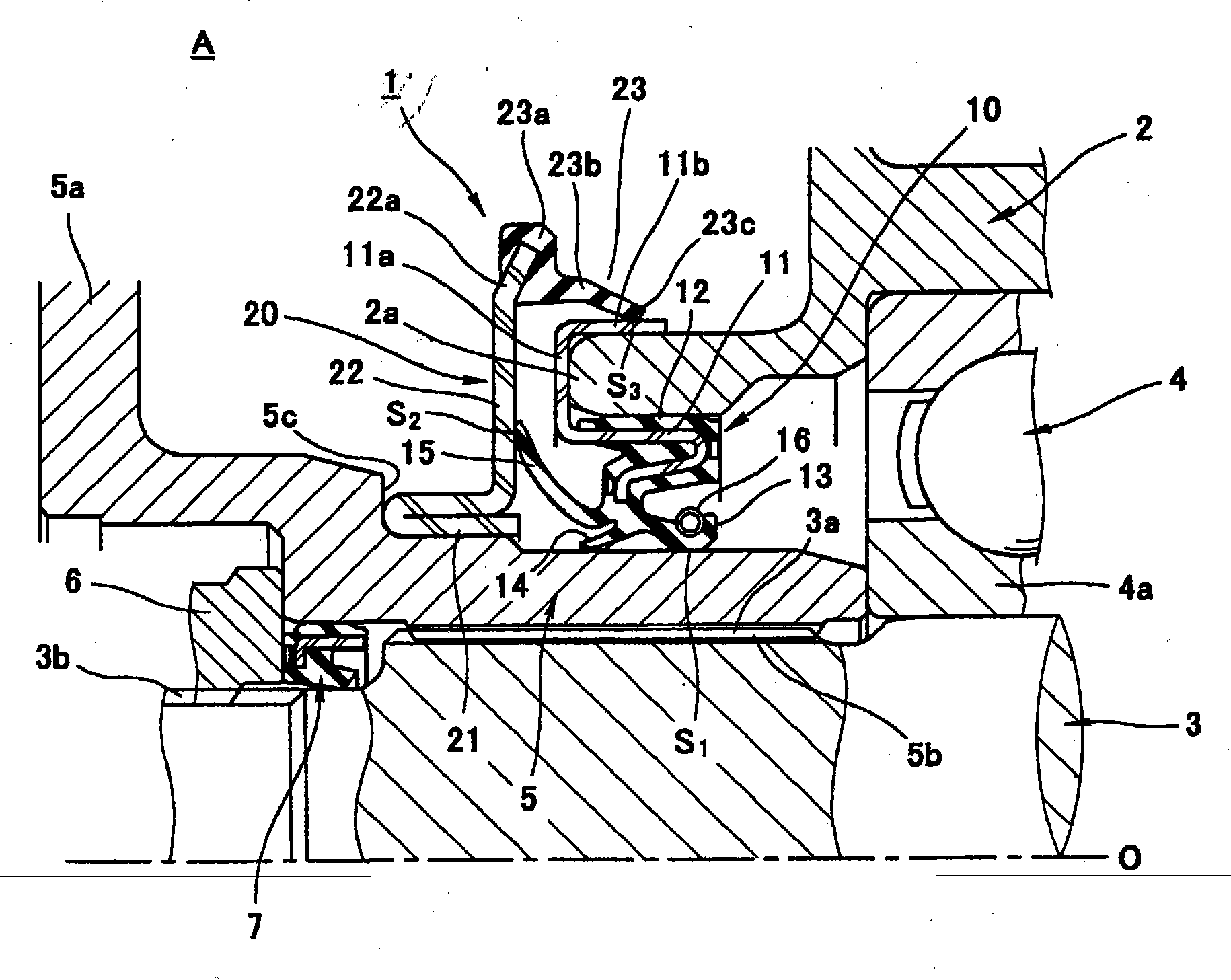
[0040] Hereinafter, embodiments of the sealing device according to the present invention will be described with reference to the drawings. figure 1 It is a half sectional view of the mounted state of the preferred embodiment of the sealing device according to the present invention cut along the plane passing through the axis O. FIG.

[0041] exist figure 1 Among them, the reference numeral 2 is a non-rotating casing on the transmission of the vehicle, the reference numeral 3 is a rotating shaft which is inserted through the above-mentioned casing 2 and is rotatably supported around the axis O through the bearing 4, and the reference numeral 5 It is a sleeve which is located on the inner peripheral side of the opening end portion 2 a of the housing 2 and is externally inserted into the rotating shaft 3 . In addition, the rotating shaft 3 and the sleeve 5 correspond to the rotating body of Claim 1.

[0042] The sleeve 5 is positioned on the outer side in the axial direction ...


PUM


Abstract

A sealing device (1) for sealing the periphery etc. of a shaft of a portion likely to be exposed to muddy water etc. coming from the outside (A). The sealing device (1) prevents as far as possible entry of muddy water etc. into a sliding section (S1) of an oil seal lip (13). To achieve this, the sealing device (1) has an oil seal (10) mounted on the inner peripheral surface of an opening end (2a) of a non-rotating housing (2), and also has a slinger (20) mounted on a rotating body (5), inserted through the housing (2), so as to be located on the axially outward side of the oil seal (10). The oil seal (10) is formed from a rubber-like elastic material and integrally with a metal reinforcement ring (11). The oil seal (10) has the oil seal lip (13) in intimate slidable contact with the outer peripheral surface of the rotating body (5), and also has a side lip (15) in intimate slidable contact with the slinger (20). The reinforcement ring (11) has a sliding tube section (11b) located on the outer diameter side of a sliding section (S2) of the side lip (15) in a manner exposed from the rubber-like elastic material. An external seal lip (23) provided on an outer diameter section (22a) of the slinger (20) is in intimate slidable contact with the outer peripheral surface of the sliding tube section (11b).

Description

technical field [0001] The present invention relates to a sealing device for sealing the shaft circumference of a transmission device and a wheel bearing device of a vehicle, etc., which are easily exposed to external muddy water, etc. The sealing device of the structure of the sliding part. Background technique [0002] Sealing devices used in vehicle transmissions and wheel bearing devices are prone to splashing from external mud and water, so it is necessary to prevent mud and water from entering the sliding part of the oil seal lip as much as possible to prevent the sealing performance of the oil seal lip as much as possible. decline. figure 2 It is a half cross-sectional view of an example of a conventional sealing device cut along a plane passing through the axis O in a mounted state. [0003] That is, in figure 2 Among them, reference numeral 2 is a casing of the transmission device, reference numeral 3 is a rotating shaft which is inserted through the above-mentio...

Claims


Application Information

Patent Timeline
Patent Type & Authority Applications(China)
IPC IPC(8): F16J15/32F16C33/78F16J15/3232
CPCF16J15/3264F16C2326/02F16C33/805F16C33/7876F16C33/7896F16C33/7886F16C2326/06F16C19/06
Inventor 中川岳洋
Owner NOK CORP
Why Eureka
Eureka Blog
Learn More