
Coding method, decoding method, coding apparatus, decoding apparatus, program, and integrated circuit

An encoding method and an encoding technology, which are applied in the field of encoding, decoding, encoding device, decoding device, program and integrated circuit, can solve the problems that cannot be fully utilized, cannot guarantee the decoding of view components, and cannot restrict the size of access units, etc.

Active Publication Date: 2010-11-10
PANASONIC INTELLECTUAL PROPERTY CORP OF AMERICA
View PDF5 Cites 0 Cited by
  • Summary
  • Abstract
  • Description
  • Claims
  • Application Information

AI Technical Summary

Problems solved by technology

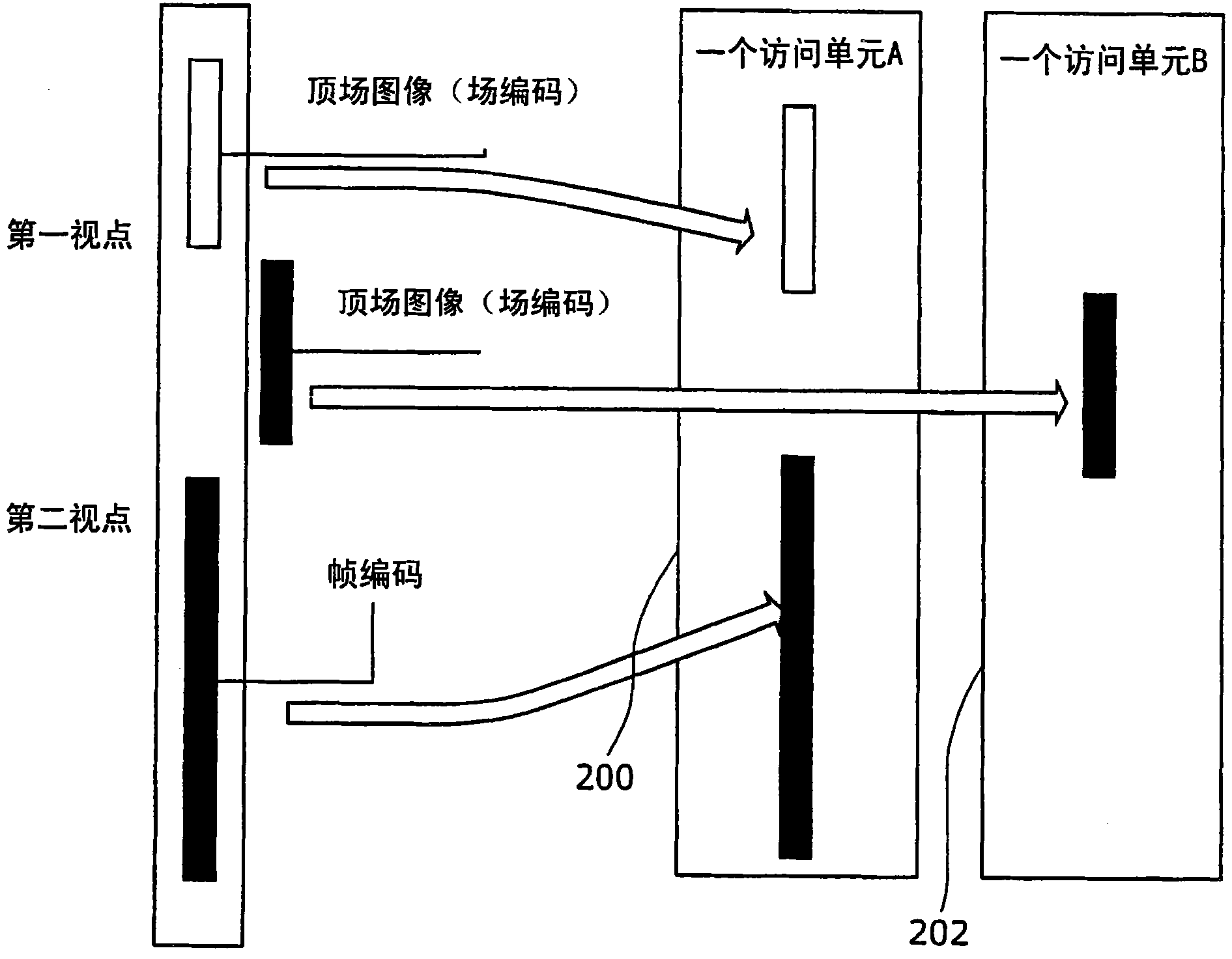
Therefore, the frame image of view 2 in access unit A cannot fully utilize the inter-view prediction from view 1, so the compression efficiency decreases
[0009] The problem with this is that each access unit container does not always have all images (ie, view components) with different viewpoints.
Therefore, the size of each access unit cannot be constrained by the constraints defined by the buffer model specified by the video specification in order to ensure proper encoding of compressed video
[0010] Another problem with the prior art (Multi-View Video Coding Specification) is that there is a constraint set for limiting the size of an Access Unit Container that includes images with multiple viewpoints (i.e., as defined in the MVC specification view component)
[0011] Constraints defined to limit the maximum size of an access unit do not guarantee that each view component within an access unit is properly decoded when each view is decoded separately by an independent decoder

Method used


Image

  • Coding method, decoding method, coding apparatus, decoding apparatus, program, and integrated circuit
  • Coding method, decoding method, coding apparatus, decoding apparatus, program, and integrated circuit
  • Coding method, decoding method, coding apparatus, decoding apparatus, program, and integrated circuit

Examples


Embodiment approach 1

[0060] Figure 4 It is a functional block diagram of the encoding device 10 according to Embodiment 1 of the present invention. The coding device 10 is a device for coding the image of viewpoint 1 and the image of viewpoint 2, such as Figure 4 As shown, an access unit definition unit 20 and a view component encoding unit 800 are provided. The image at viewpoint 1 is an interlaced moving image (first image group) in which the object is captured from the first viewpoint. The image at viewpoint 2 is an interlaced moving image (second image group) in which the same object is captured from a second viewpoint different from the first viewpoint.

[0061]The access unit definition unit 20 includes a coding unit determination unit 30 and a field type determination unit 40 , and defines an access unit composed of images corresponding to viewpoint 1 and viewpoint 2 . The "corresponding image" here refers to, for example, an image taken at the same time, and the same PTS (Presentation...

Embodiment approach 2

[0130] By recording a program for realizing the configuration of the image encoding method or the image decoding method described in the above-mentioned embodiments on a storage medium, the processing shown in the above-mentioned embodiments can be easily implemented in an independent computer system. The storage medium may be a magnetic disk, optical disk, magneto-optical disk, IC card, semiconductor memory, etc., as long as the program can be recorded.

[0131] Furthermore, application examples of the image encoding method and image decoding method described in the above-mentioned embodiments and a system using them will be described here.

[0132] Figure 13 It is a diagram showing the overall configuration of the content supply system ex100 for realizing the content distribution service. The area for providing communication services is divided into desired sizes, and base stations ex106 to ex110 serving as fixed wireless stations are installed in each cell.

[0133] The ...

Embodiment approach 3

[0169] The image coding method and device, and the image decoding method and device described in the above-mentioned embodiments are generally realized by an LSI that is an integrated circuit. As an example, Figure 20 Shows the structure of LSIex500 on a single chip. The LSI ex500 includes elements ex501 to ex509 described below, and the elements are connected via a bus ex510 . The power supply circuit unit ex505 supplies electric power to each unit while the power supply is turned on, thereby starting to be in an operable state.

[0170] For example, when performing encoding processing, the LSI ex500 receives AV signal input from the microphone ex117 and the camera ex113 through the AVI / O ex509 under the control of the controller ex501 including the CPU ex502, the memory controller ex503, and the stream controller ex504. The input AV signal is temporarily stored in an external memory ex511 such as SDRAM. According to the control of the control unit ex501, the accumulated ...


PUM


Abstract

An encoding method including an access unit defining step (S502 to S508) for defining access units, and an encoding step (S526) for encoding, per access unit, the images that constitute said access unit. The access unit defining step (S502 to S508) includes an encoding unit determining step (S502) for determining whether to uniformly encode the images included in an access unit in field units or frame units, and a field type determining step (S504 to S508) for determining whether to uniformly encode the images in the top field or bottom field when it has been determined to encode the images included in the access unit in field units. Further, the encoding step (S526) encodes, per access unit, images in the formats that have been determined in the encoding unit determining step (S526) and the field type determining step (S502 to S508).

Description

technical field [0001] The present invention can be used for encoding method and decoding method of all multimedia data, especially can be used for encoding method and decoding method of H.264 / MPEG-4 AVC multi-viewpoint image. Background technique [0002] Three-dimensional images have been around for a long time. There are various methods of providing a three-dimensional visual effect to the viewer. One of these methods is to display two images respectively to the left and right eyes of the viewer. This is called stereo photography using two cameras to capture two images. As one of the conventionally used techniques for displaying stereoscopic images, there is a method of applying filtering to color components so as to be able to be viewed separately with one eye. In this technique, the resolution of images provided to each eye becomes low. [0003] With recent advances in display technology, viewers are now able to view images with the highest resolution with each eye....

Claims


Application Information

Patent Timeline
IPC IPC(8): H04N7/32H04N13/02H04N13/00H04N19/00H04N19/102H04N19/136H04N19/146H04N19/169H04N19/196H04N19/423H04N19/46H04N19/50H04N19/503H04N19/593H04N19/597H04N19/61H04N19/625H04N19/70H04N19/85H04N19/91
CPCH04N19/00781H04N19/00278H04N19/00187H04N19/00884H04N19/00193H04N19/00048H04N13/0048H04N19/00266H04N19/0009H04N13/0066H04N19/00769H04N13/161G11B27/3027G11B27/329H04N5/765H04N5/85H04N9/8042H04N9/8205H04N9/8211H04N9/8233H04N13/178H04N13/183H04N13/189G11B2220/213G11B2220/2541H04N19/597H04N19/70H04N19/172H04N19/15H04N19/112H04N19/124H04N19/152H04N13/00
Inventor 林宗顺西孝启柴原阳司
Owner PANASONIC INTELLECTUAL PROPERTY CORP OF AMERICA
Learn More