Coating device and coating method for optical cement

A gluing device and optical glue technology, applied to the surface coating liquid device, coating, input/output process of data processing, etc., can solve the problems of increased production cost, waste, low product yield, etc., to achieve The effect of improving work efficiency, reducing production costs and improving yield

Inactive Publication Date: 2012-01-18
徐天龙
View PDF0 Cites 0 Cited by
  • Summary
  • Abstract
  • Description
  • Claims
  • Application Information

AI Technical Summary

Problems solved by technology

[0006] The existing gluing method mainly has the following disadvantages: 1. The above processes generally adopt manual operation, so it is related to the proficiency of the workers and affects the gluing efficiency
2. The yield rate of the product is low. When the solid optical adhesive is bonded to the ITO conductive layer, bubbles will generally be generated. The current method of defoaming is to use heat and pressure. This method only makes the edges The air bubbles have a chance to be released, and most of the air bubbles that are not on the edge are all evenly dispersed into the colloid, which will reduce the light transmittance of the colloid. In the prior art, the yield rate of optical glue coated by solid lamination method is only 50%. %
3. Low profit, unqualified products including scrapping and rework of the entire touch screen will cause a lot of waste and increase production costs

Method used


Image

  • Coating device and coating method for optical cement
  • Coating device and coating method for optical cement
  • Coating device and coating method for optical cement

Examples


Embodiment Construction

[0037] In order to further understand the present invention, the preferred embodiments of the present invention are described below in conjunction with the examples, but it should be understood that these descriptions are only to further illustrate the features and advantages of the present invention, rather than limiting the claims of the present invention.

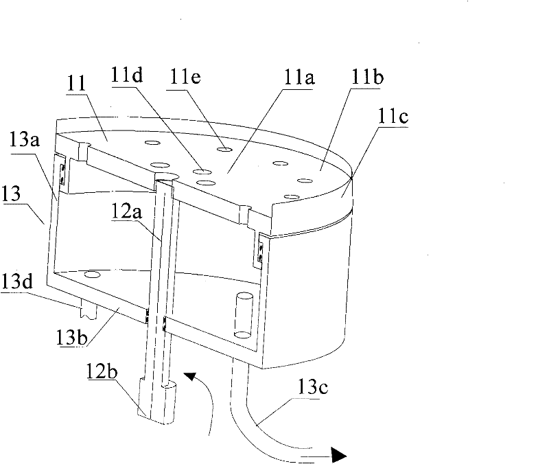
[0038] See image 3 , is a schematic cross-sectional view of a bearing of a specific embodiment of the optical glue coating device provided by the present invention. Such as image 3 As shown, the gluing device includes a circular tray 11 carrying an ITO conductive layer, and the tray 11 includes a circular bearing portion 11a bearing an ITO conductive layer and an edge portion 11b connected to the outer periphery of the circular bearing portion 11a, and the circular bearing portion 11a and the edge portion 11b can be integrally formed, and there is an upright side wall 11c on the outer periphery of the edge portion, an...


PUM


Abstract

The invention provides a coating device for optical cement, which comprises a tray for bearing a conductive layer, a driving device arranged below the tray and used for driving the tray to rotate, and a vacuum tank arranged below the tray and used for forming negative pressure to adsorb the conductive layer on the tray, wherein the tray comprises a circular bearing part for bearing the conductivelayer and an edge part connected on the periphery of the circular bearing part, and the circular bearing part is provided with a vacuum passage; the vacuum tank comprises a circular shell and a bottom wall connected at the bottom of the circular shell; and a rotating shaft of the driving device passes through the bottom wall and is connected with the tray, the top end of the circular shell is rotationally and hermetically connected with the tray, and the vacuum passage is communicated with the vacuum tank. The coating device provided by the invention can realize automatic coating of the conductive layer, is favorable for realizing continuous and stable production of the coating process, and improves the production efficiency. Moreover, the liquid optical cement can avoid bubbles during rotary coating, and is favorable for improving the yield of a product.

Description

technical field [0001] The invention relates to the production of touch screens, in particular to a glue coating device and a glue coating method for optical glue. Background technique [0002] With the high performance and diversified development of various electronic devices such as mobile phones and touch navigation systems, it has become a common technology for these electronic devices to install light-transmitting touch panels in front of display elements such as liquid crystals. Through the touch screen, the user visually confirms the display content of the display element located on the back of the touch screen, and presses the touch screen with a finger or a pen to perform operations to realize various functions of the electronic device. [0003] According to different working principles and transmission media of touch screens, existing touch screens are divided into five types: resistive, surface capacitive, projected capacitive, surface acoustic wave, and infrared....

Claims


Application Information

Patent Timeline
Patent Type & Authority Patents(China)
IPC IPC(8): B05C9/08B05C11/08B05C11/10B05C13/02B05D7/00B05D3/00B05D3/06G06F3/045
Inventor 徐天龙
Owner 徐天龙
Why Eureka
Try Eureka