
Connecting structure for nested composite sections

A technology of composite profiles and connecting structures, which is applied in the connection of rods, connecting members, and truss structures, etc., can solve the problems of many components of the connecting structure, unfavorable positioning of the connecting structure, inconvenient assembly and disassembly, etc., so as to improve the connection accuracy and Connection strength, preventing deformation and dislocation, reducing deformation effect

Inactive Publication Date: 2010-11-17
朱建华
View PDF6 Cites 11 Cited by
  • Summary
  • Abstract
  • Description
  • Claims
  • Application Information

AI Technical Summary

Problems solved by technology

However, the connection structure of this patent has many components and a complex structure, and the connection fixture is fixed on the inner wall of the beam, which is inconvenient to assemble and disassemble, and is also not conducive to the positioning of the connection structure relative to the column and the beam

Method used


Image

  • Connecting structure for nested composite sections
  • Connecting structure for nested composite sections
  • Connecting structure for nested composite sections

Examples


Embodiment Construction

[0023] The present invention will be further described in detail below in conjunction with the accompanying drawings and embodiments.

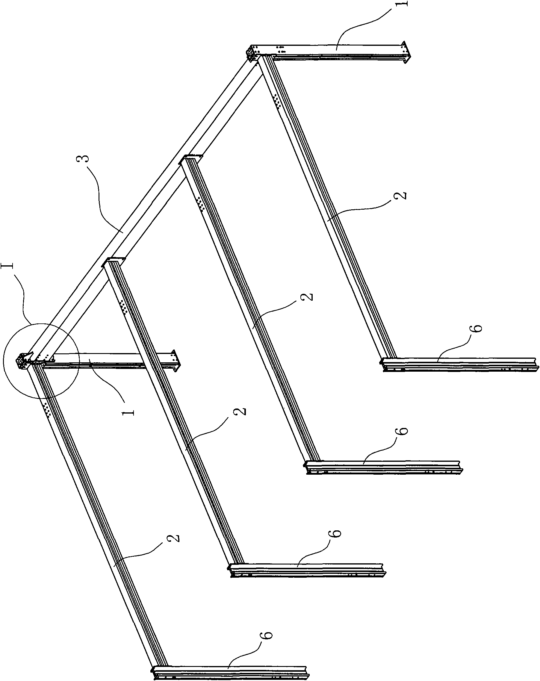
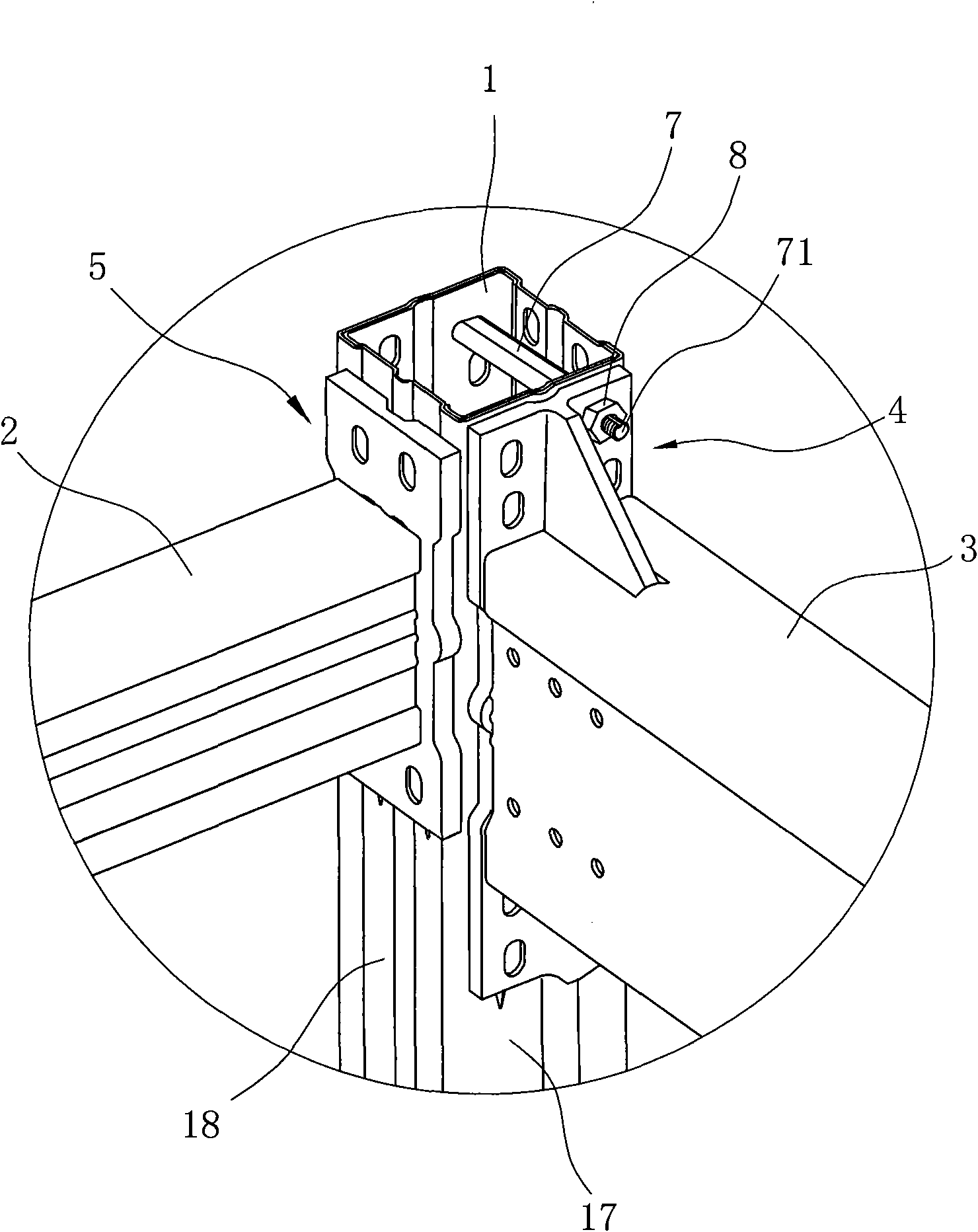
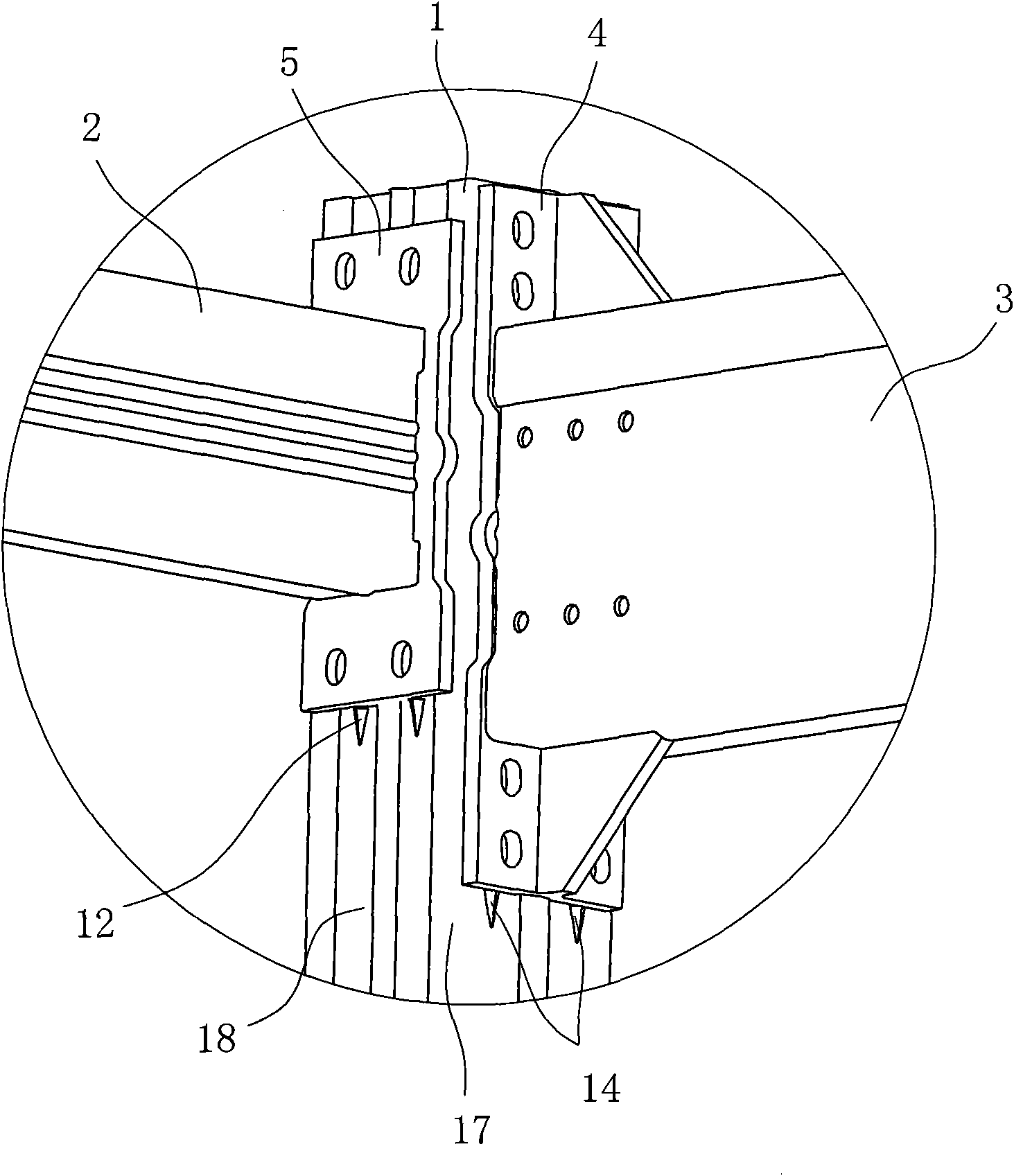
[0024] like Figure 1 to Figure 11 Shown is the beam-column connection structure diagram shown in the three-dimensional garage underframe of this embodiment. The three-dimensional garage underframe includes a column 1, a vertical beam 3, a front beam 2 and a rear column 6, wherein the column 1 and the vertical beam 3 and the vertical connection between the column 1 and the front beam 2 are the invention points of this embodiment. The molding of the column 1, the front beam 2 and the longitudinal beam 3 of this embodiment is different from the traditional casting process. In this embodiment, Column 1, front beam 2 and longitudinal beam 3 respectively adopt nested composite profile structure, and each beam column is cold-rolled respectively, and two first members and second members of the same shape and size are staggered and embraced to form a ...


PUM


Abstract

The invention discloses a connecting structure for nested composite sections. The connecting structure comprises an upright post and a cross beam which are respectively crossly nested by elongated members to form a thin-wall cylinder, and is characterized in that: the upright post and the cross beam are vertically connected through a connecting joint; the connecting joint comprises a bottom plate and a lug boss, wherein a hole cavity is formed on the lug boss along the direction vertical to the bottom plate; the lug boss and the cross beam are in inserted connection, and the bottom plate are connected with the side walls of the upright post through a fastening piece; convex ribs are molded on an outer side wall of the upright post along the length direction; a guiding grooves which are matched with the convex ribs are formed at the bottom of the bottom plate; and the outer side wall of the upright post is also provided with protrusions which prop against the lower edge of the bottom plate. Compared with the prior art, the connection structure has the advantages that: due to vertical connection of the detachable connecting joint, the bottom plate of the connecting joint and the upright post are connected by irregular bolts, and the connecting structure realizes detachable connection, and also can guarantee tight adhesion of the side walls of two sides of the upright post with the composite structure; and seamless connection between the side walls of two sides of the upright post is realized, and the strength and rigidity of the upright post are obviously improved.

Description

technical field [0001] The invention relates to a connection structure, in particular to a vertical connection structure between beams and columns using nested composite profiles. Background technique [0002] In the prior art, the columns or beams used in the frame structure devices such as the garage base frame, the display cabinet frame or the display rack are mostly formed by casting, and the vertical connection between the columns and the beams is mostly fixed by direct welding, or first Weld a connection plate on the column (beam), and then fix the beam (column) to the connection plate. However, when the welding method is used for on-site installation, the workload is heavy, the operation is inconvenient, and the columns or beams are easily deformed by heat. However, in the way of pre-welding the connecting plates on the beams and columns, the beams and columns are not of equal cross-section due to the convexity of the connecting plates. Profiles cause troubles in pac...

Claims


Application Information

Patent Timeline
IPC IPC(8): E04B1/58
CPCE04B2001/2418E04C3/07E04C2003/043E04B2001/2451F16B7/18E04C2003/0465E04B2001/2415E04B1/24E04B2001/2472E04B1/0046E04B2001/2463E04C2003/0413
Inventor 朱建华
Owner 朱建华
Learn More