Assembly device, set of two parts assembled by such a device and warp frame of a machine for forming the shed including such a set

A technology of fastening device and forming machine, applied in the direction of threaded fasteners, locking fasteners, connecting components, etc., can solve problems such as incompatibility, and achieve the effect of compact device and suitable for disassembly

Active Publication Date: 2010-11-17
STAUBLI FAVERGES SA
View PDF6 Cites 1 Cited by
  • Summary
  • Abstract
  • Description
  • Claims
  • Application Information

AI Technical Summary

Problems solved by technology

Therefore, the device is not suitable for assembling the two components of the shedding machine

Method used


Image

  • Assembly device, set of two parts assembled by such a device and warp frame of a machine for forming the shed including such a set
  • Assembly device, set of two parts assembled by such a device and warp frame of a machine for forming the shed including such a set
  • Assembly device, set of two parts assembled by such a device and warp frame of a machine for forming the shed including such a set

Examples


Embodiment Construction

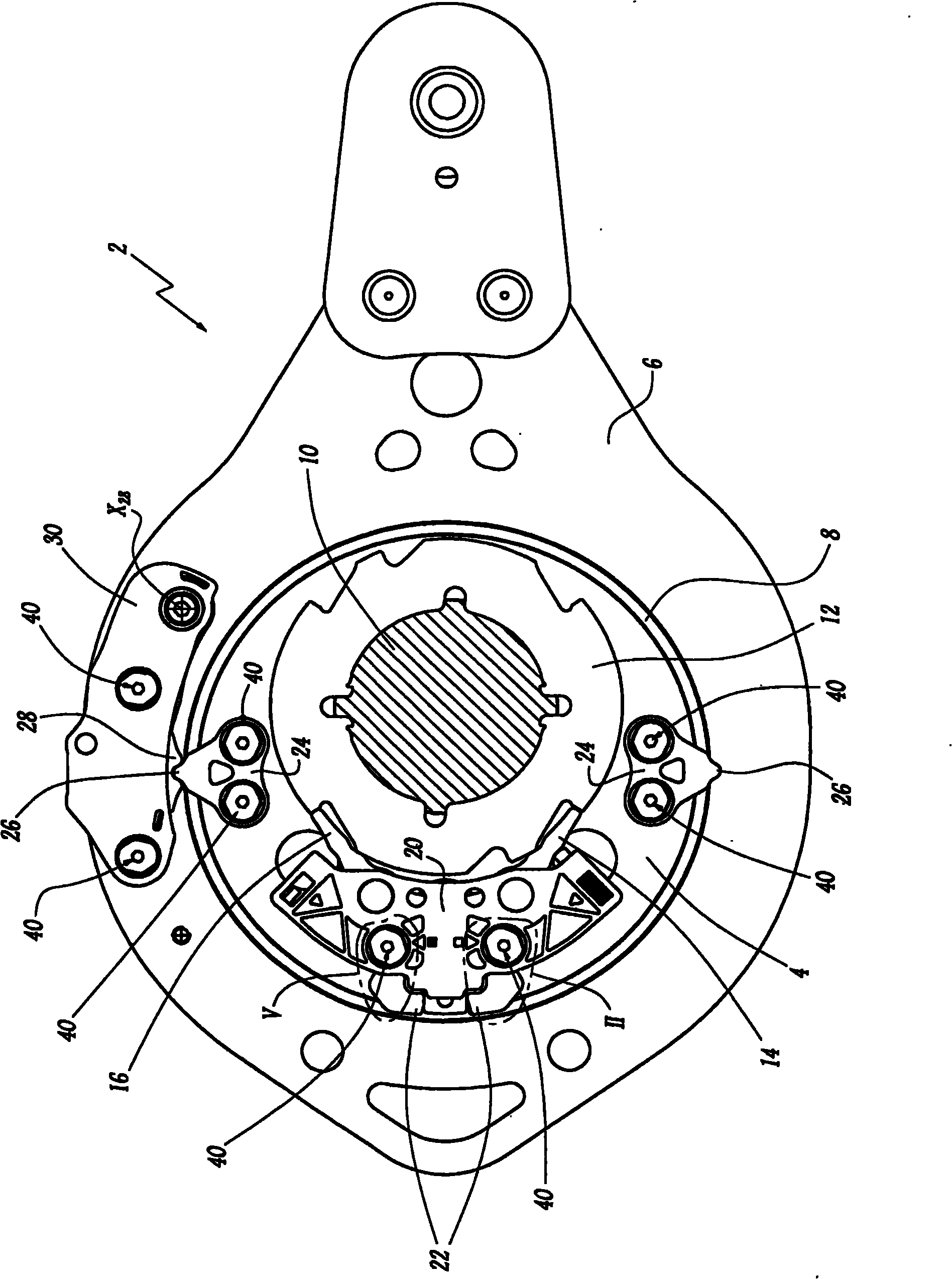
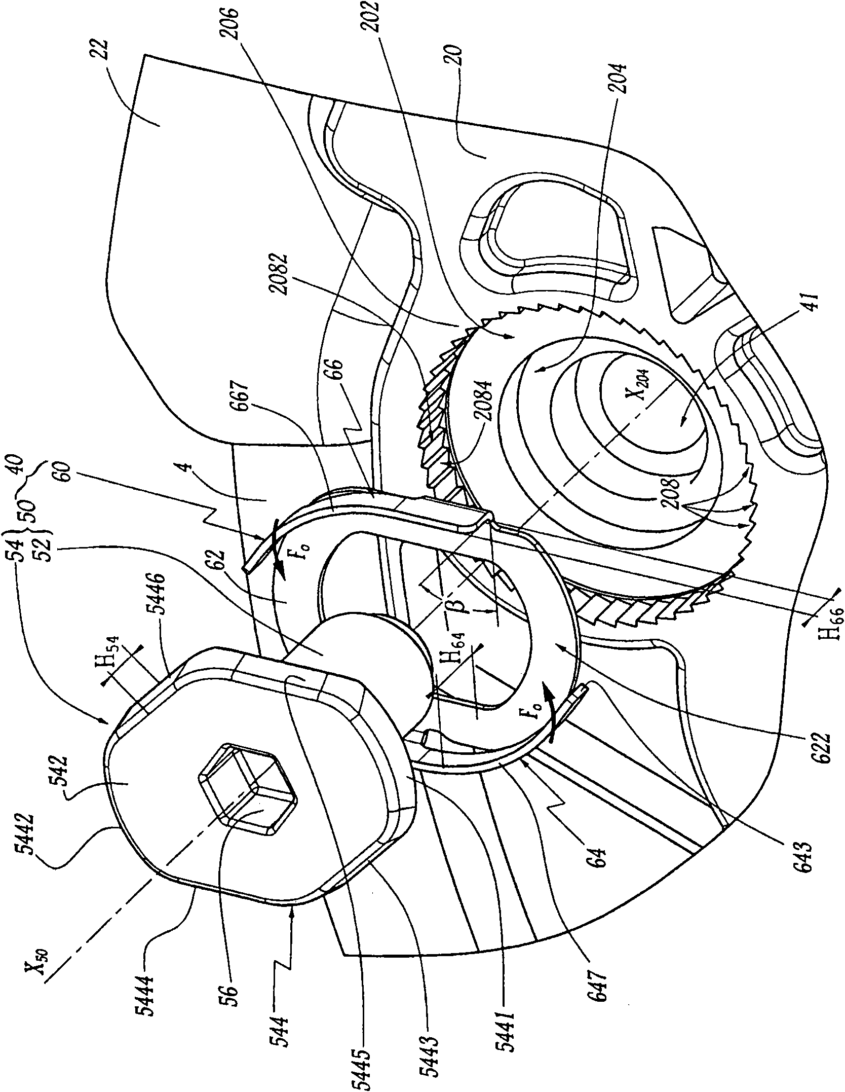
[0030] figure 1 A part of the heald frame lifting unit 2 shown in includes an eccentric disk 4 with an opening for an oscillating connecting rod 6 movably mounted thereon, with ball bearings 8 arranged between them. The connecting rod 6 is intended to be connected to a pulling mechanism engaged with the heald frame by means (not shown) comprising a pivot arm. The main shaft 10 driven by intermittent rotation rotates together with the drive disc 12 and pauses every half circle. Detents 14 and 16 controlled in a known manner selectively fasten the eccentric disc 4 to the disc 12 according to the movement transmitted to the heald frame. Detent pins 14 and 16 are made by Figure 2-Figure 7 The plastic material cap 20 of the eccentric disk 4 is held against the eccentric disk 4 by two fastening means 40 shown in detail in . Two guide members 22, generally called "ramps", are provided between the cap 20 and the eccentric disc 4, and they protrude radially from the (not shown) ex...


PUM


Abstract

An assembly device (40) for assembling at least two parts (4, 20, 22) of a machine (2) for forming the shed, includes a screw (50) equipped with a threaded rod (52) and a head (54) comprising a pair of two adjacent side edges (5443-5446) forming a non-straight angle between the two adjacent side edges, where the head (54) of the screw (50) is provided with a hollow mark (56) for receiving a tool driving the screw to rotate. A blocking ring (60) is mounted around the screw (50), and has an annular part (62) supported against a face (546) of the head directed towards the rod (52) and at least one tab (64, 66). The tabs has first parts (648, 668) placed against first edges (5444, 5445) of the two adjacent side edges (5443-5446) along a radial direction with respect to a central axis of the screw, and the second parts of the tabs face to the second edges (5443, 5446) of the two adjacent side edges, in the radial direction, and is suitable to be close to (F0) or separated from the second edges (5443, 5446) by elastic deformation of the tab.

Description

Background technique [0001] In the field of shedding, it is necessary to assemble certain parts of the heald frame lifting unit of the machine during the machine manufacturing process. The hoisting unit is subject to high levels of acceleration and vibration and has a compact structure suitable for the cut size of the loom. For example, FR-A-2899602 shows a rotary dobby in which the cover is mounted on an eccentric disc and holds the needle selector in place. The cover is bolted to the eccentric disc. Due to the aforementioned vibrations and accelerations, such bolts are prone to loosen during dobby use. Likewise, the tongues of the bolts having serrated projections for cooperating with the locking arms are also secured to the eccentric disc with bolts that tend to loosen during use. [0002] However, in cases where special pressure equipment is not necessary, mounting with bolts is advantageous over rivets. Also, thread locking is not recommended as disassembly of the she...

Claims


Application Information

Patent Timeline
Patent Type & Authority Applications(China)
IPC IPC(8): F16B39/24D03C1/00
CPCD03C1/00F16B39/32F16B39/10
Inventor R·诺桑蒂
Owner STAUBLI FAVERGES SA
Why Eureka
Try Eureka