Three-phase power input phase-loss detection circuit
A technology of phase loss detection and three-phase power supply, which is applied in the direction of power supply testing, multi-phase network asymmetry measurement, etc., can solve the problems affecting the reliability of the circuit, affecting the anti-interference ability of the circuit, and many peripheral devices, so as to facilitate the digital signal Processing, meeting the needs of phase loss detection, and strong anti-interference ability
- Summary
- Abstract
- Description
- Claims
- Application Information
AI Technical Summary
Problems solved by technology
Method used
Image

Examples
no. 1 approach
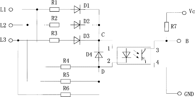
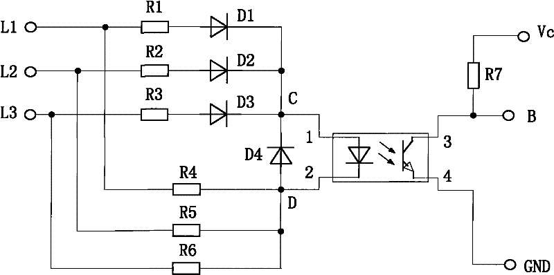
[0026] figure 1 It is the circuit principle diagram of the first embodiment of the three-phase power supply input phase loss detection circuit of the present invention. The phase loss detection circuit includes a first current-limiting resistor R1, a second current-limiting resistor R2 and a third current-limiting resistor R3 respectively connected to the three-phase input L1, L2, L3, including a first diode D1, a second two The pole tube D2 and the third diode D3, the anodes of the three diodes are respectively connected in series with the three current limiting resistors, the cathodes of the three diodes are connected to the input terminal 1 of the primary side of the optocoupler, and the three-phase inputs L1 and L2 are respectively connected , the fourth resistor R4 of L3, the fifth resistor R5 and the sixth resistor R6, wherein R4 is connected in parallel with R1 and D1, R5 is connected in parallel with R2 and D2, R6 is connected in parallel with R3 and D3, and the three ...
no. 2 approach
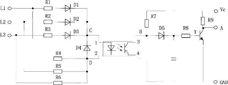
[0031] figure 2 It is the circuit principle diagram of the second embodiment of the three-phase power supply input phase loss detection circuit of the present invention. Its similarities with the first embodiment will not be repeated here. Compared with the first embodiment, the three-phase input power supply phase loss detection circuit also includes a level flipping circuit with one end connected to the pull-up resistor R7 and the other end connected to the output terminal 3 of the secondary side of the optocoupler. The level flipping circuit is connected in parallel the pull-up resistor R7.
[0032] The level inversion circuit includes a fifth diode D5 whose anode is connected to the output terminal 3 of the secondary side of the optocoupler. The cathode of the fifth diode D5 is connected to the base of the transistor T through the eighth resistor R8. The flipping circuit further includes a pull-up resistor R9 connected to the collector of the transistor T and a capacito...
PUM
 Abstract
Description
Claims
Application Information
 - R&D
- Intellectual Property
- Life Sciences
- Materials
- Tech Scout
- Unparalleled Data Quality
- Higher Quality Content
- 60% Fewer Hallucinations
Browse by: Latest US Patents, China's latest patents, Technical Efficacy Thesaurus, Application Domain, Technology Topic, Popular Technical Reports.
© 2025 PatSnap. All rights reserved.Legal|Privacy policy|Modern Slavery Act Transparency Statement|Sitemap|About US| Contact US: help@patsnap.com