Manufacture method of optical module

A manufacturing method and technology of optical modules, applied in optics, manufacturing tools, nonlinear optics, etc., can solve problems such as the separation of lens structure and glass substrate, the reduction of production yield of birefringent lenses, etc., and achieve the effect of improving production yield

Inactive Publication Date: 2010-11-17
AU OPTRONICS CORP
View PDF6 Cites 8 Cited by
  • Summary
  • Abstract
  • Description
  • Claims
  • Application Information

AI Technical Summary

Problems solved by technology

However, in the process of splitting, the lens structure is often separated from the glass substrate, which greatly reduces the production yield of birefringent lenses

Method used


Image

  • Manufacture method of optical module
  • Manufacture method of optical module
  • Manufacture method of optical module

Examples


Embodiment Construction

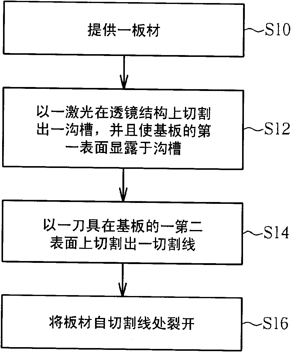
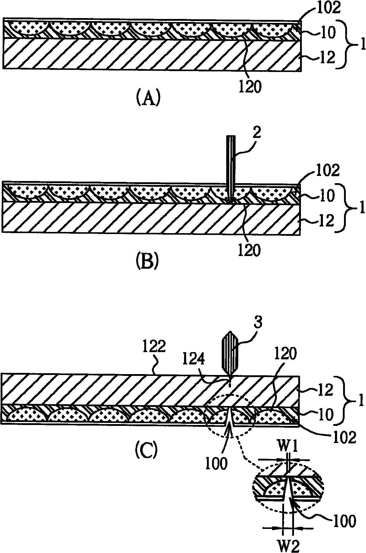
[0043] see figure 1 as well as figure 2 , figure 1 It is a flow chart of a manufacturing method of an optical module according to an embodiment of the present invention, figure 2 for matching figure 1 Schematic diagram of the process. First, step S10 is performed to provide a plate 1, wherein the plate 1 includes a lens structure 10 and a substrate 12, and the lens structure 10 is formed on a first surface 120 of the substrate 12, as figure 2 (A) shown. In this embodiment, the substrate 12 may be a glass substrate, but not limited thereto. Next, step S12 is executed, a groove 100 is cut on the lens structure 10 with a laser 2, and the first surface 120 of the substrate 12 is exposed in the groove 100, as figure 2 (B) with figure 2 (C) shown. Next, step S14 is performed, turning the board 1 over, and cutting a cutting line 124 on a second surface 122 of the substrate 12 with a cutter 3, wherein the second surface 122 is opposite to the first surface 120, and the cu...


PUM

PropertyMeasurementUnit
widthaaaaaaaaaa
widthaaaaaaaaaa
widthaaaaaaaaaa

Abstract

The invention discloses a manufacture method of an optical module, comprising the following steps of supplying a plate, wherein the plate comprises a lens structure and a substrate, and the lens structure is formed on the first surface of the substrate; cutting a groove by a laser on the lens structure and enabling the first surface of the substrate to be exposed from the groove; cutting a cutting line by a cutter on the second surface of the substrate, wherein the second surface is relative to the first surface, and the cutting line is relative to the groove; and cracking the plate starting from the cutting line. In the invention, because the groove is cut on the lens structure by utilizing the laser firstly to enable the substrate to be exposed from the groove, and then the cutting line is cut on the substrate corresponding to the position of the groove by utilizing the cutter, when the plate is splintered along the cutting line, the lens structure can be ensured not to be separated from the substrate, thereby improving the production yield rate of the optical module.

Description

technical field [0001] The invention relates to a manufacturing method of an optical module and a display device, in particular to a cutting method that can be used in a birefringent lens process. Background technique [0002] Generally speaking, the principle of artificial stereoscopic image imaging is to simulate the real situation, produce real three-dimensional objects, or project different images (paired stereoscopic images) to the left and right eyes respectively, and provide additional depth information to form a stereoscopic image. The known stereoscopic imaging technologies can be divided into three types: holographic, planar and paired stereoscopic. Since the holographic and planar displays have the disadvantages of a large amount of data processing difficulties and poor display effects, research on stereoscopic image displays in recent years has focused on paired stereoscopic image displays. Among the paired stereoscopic images, the spatial multiplexed stereoscop...

Claims


Application Information

Patent Timeline
Patent Type & Authority Applications(China)
IPC IPC(8): G02F1/1333G02F1/1335B23K26/00B23K26/38
Inventor 黄义雄陈文龙武柏玮臧华安
Owner AU OPTRONICS CORP
Why Eureka
Try Eureka