Radio frequency power amplifier with push-pull structure

A technology of radio frequency power and power amplifying circuit, applied in the field of push-pull structure radio frequency power amplifier, can solve the problems of low linearity of push-pull structure power amplifier, slow development of push-pull structure power amplifier, hindering the development of radio frequency power amplifier, etc. Achieve the effects of high stability, reduced DC loss, and high circuit efficiency

Inactive Publication Date: 2010-11-17
SUZHOU INNOTION TECH
View PDF5 Cites 3 Cited by
  • Summary
  • Abstract
  • Description
  • Claims
  • Application Information

AI Technical Summary

Problems solved by technology

However, the development of push-pull power amplifiers based on HBT technology is slow
Another reason for this phenomenon is that NPN and PNP power tubes are very different in terms of magnification and working speed. The two branches of the output stage of the push-pull structure do not have perfect symmetry, resulting in push-pull structure. The linearity of the power amplifier is not high. This shortcoming makes the NPN-PNP compensation HBT push-pull structure not applied to the field of RF power amplifier for a long time, which hinders the development of push-pull structure RF power amplifier based on HBT technology.

Method used


Image

  • Radio frequency power amplifier with push-pull structure
  • Radio frequency power amplifier with push-pull structure
  • Radio frequency power amplifier with push-pull structure

Examples


Embodiment

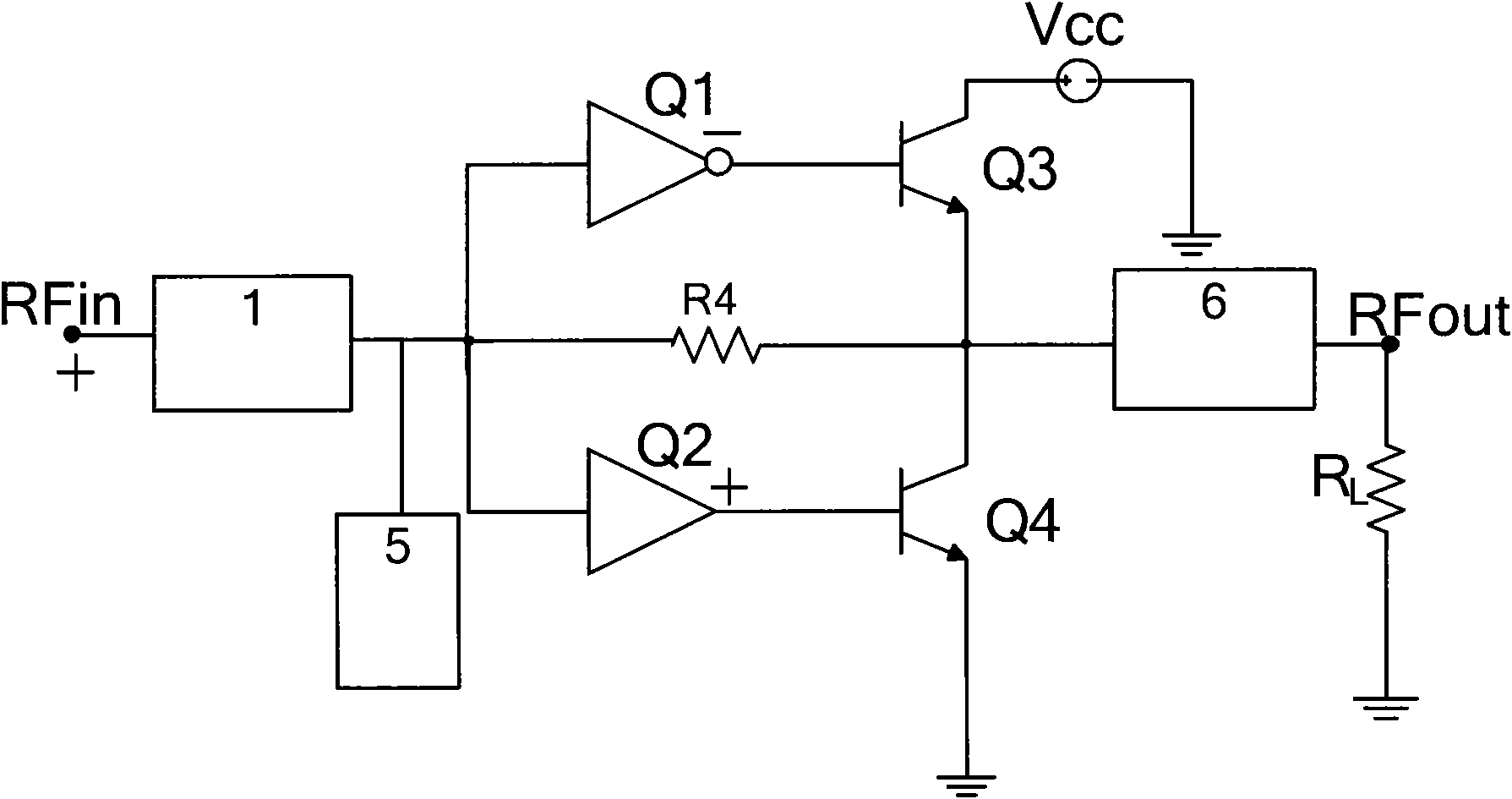
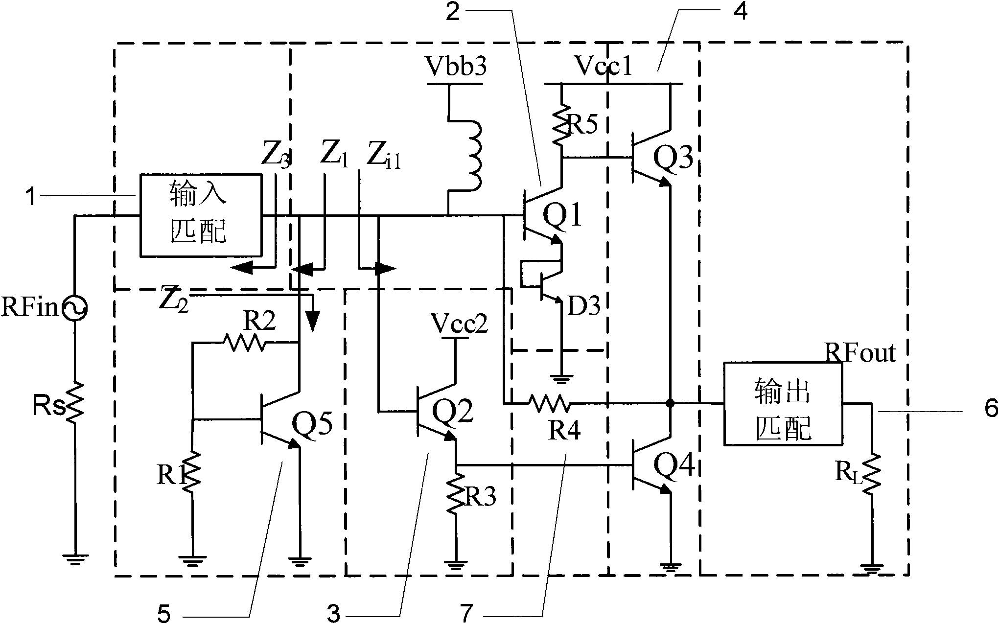
[0027] Example: such as Figure 1 to Figure 5 As shown, a radio frequency power amplifier of a push-pull structure includes an input matching network 1 connected to the input end of the power amplifier, an output matching network 6 connected to the output end of the power amplifier, and an input matching network 1 connected to the output matching network 6 The power amplifying circuit between, the power amplifying circuit comprises the first stage power amplifying circuit that is made up of the first stage upper branch circuit amplifier 2 and the first stage lower branch circuit amplifier 3, and is mainly composed of the second common collector amplifying tube Q3 and the second-stage NPN-NPN push-pull power amplifier circuit 4 composed of the second common-emitter amplifier tube Q4. The first stage upper branch amplifier 2 is an inverting amplifier mainly composed of the first common emitter amplifier tube Q1; the first stage lower branch amplifier 3 is mainly composed of the ...


PUM


Abstract

The invention discloses a radio frequency power amplifier with a push-pull structure, which comprises an input matching network connected with the input end of the power amplifier, an output matching network connected with the output end of the power amplifier and a power amplifier circuit connected between the input matching network and the output matching network, and an output-stage circuit of the power amplifier circuit is a second-stage NPN-NPN push-pull power amplifier circuit which mainly consists of a second common collector amplifier tube and a second common emitter amplifier tube. The radio frequency power amplifier with the push-pull structure can lead the push-pull structure to be applied in the field of the radio frequency power amplifiers through the HBT process, and realize the integration of linearity and efficiency.

Description

technical field [0001] The invention relates to the technical field of radio frequency integrated circuits, in particular to a radio frequency power amplifier with a push-pull structure. Background technique [0002] With the emergence of third-generation mobile communication systems, RF power amplifiers have been increasingly used in wireless communications. In order to ensure good communication quality, communication systems have increasingly stringent requirements on the efficiency and linearity of RF power amplifiers. At present, the design ideas of RF power amplifiers focus on two aspects: one is to bias the power output stage circuit to class A, the linearity of the power amplifier is effectively improved, but the efficiency is reduced; the other is to bias the power output stage circuit to If it is placed in class B, it cannot take into account linearity while obtaining efficiency. Therefore, most RF engineers choose a compromise solution - biasing the power output s...

Claims


Application Information

Patent Timeline
Patent Type & Authority Applications(China)
IPC IPC(8): H03F3/26
Inventor 高怀张晓东胡善文牛旭梁聪
Owner SUZHOU INNOTION TECH
Why Eureka
Try Eureka