
Flexible conducting material substrate and implementing method thereof

A technology of flexible conduction and realization method, applied in electrical components, magnetic field/electric field shielding, radiation element structure and other directions, can solve the problems of poor electrical conductivity, difficult to control the pressure size, unable to meet the reliability of electrical conductivity, etc., to ensure the firmness of installation , the effect of good electrical conductivity

Active Publication Date: 2010-11-17
ZTE CORP
View PDF4 Cites 9 Cited by
  • Summary
  • Abstract
  • Description
  • Claims
  • Application Information

AI Technical Summary

Problems solved by technology

However, since the fixing glue is not a good conductor, it cannot make good contact between the flexible conductive material and the ground plane around the shielded area. Therefore, if only the fixing glue is used, only the firmness of the installation can be achieved, but the reliability of the conduction cannot be satisfied.
[0006] In order to solve this problem, the existing method is to dope metal particles or conductive fibers in the fixing glue to improve the poor conductivity of the fixing glue, but since the fixing glue is also wrapped around the discrete metal particles or conductive fibers, it is necessary to Apply a certain pressure to the flexible conductive material to ensure that the metal particles will be connected to the shielded area and the flexible conductive material
However, different pressures correspond to different conductive effects, and it is difficult to control the pressure during use. Therefore, it is difficult to meet the requirements for the reliability of flexible conductive materials.

Method used


Image

  • Flexible conducting material substrate and implementing method thereof
  • Flexible conducting material substrate and implementing method thereof
  • Flexible conducting material substrate and implementing method thereof

Examples


Embodiment Construction

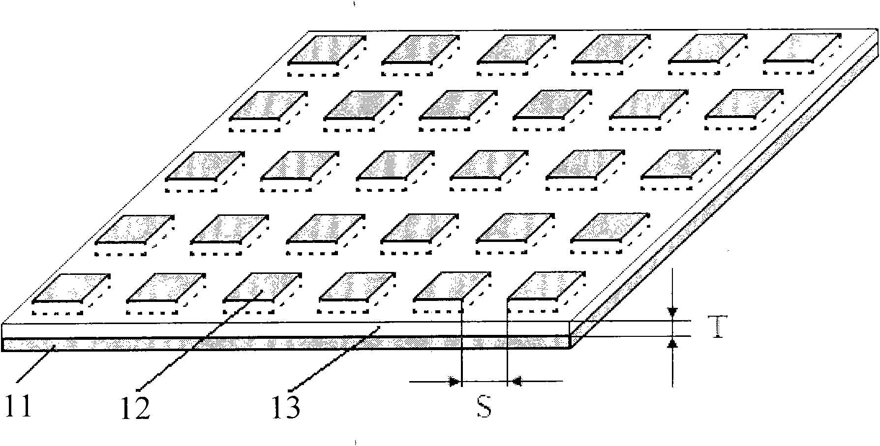
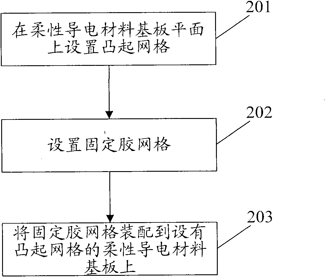
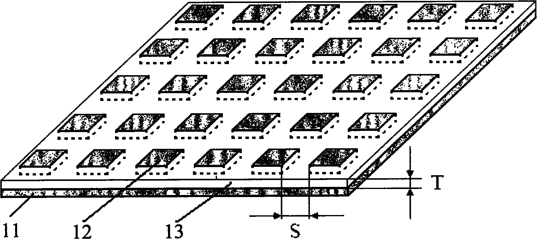
[0029] The basic idea of ​​the present invention is: setting raised grids on the plane of the flexible conductive material substrate; placing fixing glue in the grooves between the raised grids of the flexible conductive material to form the fixing glue grid.

[0030] Wherein, the raised grid of flexible conductive material is integrated with the substrate of flexible conductive material; the raised grid of flexible conductive material is intersected with the fixed glue grid, that is, each raised grid of flexible conductive material Fixing glue is distributed around each protrusion; the distance between adjacent protrusions of the flexible conductive material is set according to the wavelength of the electromagnetic wave to be shielded.

[0031] The protrusions of the flexible conductive material in the present invention can be arranged in regular structures such as cylinders and cubes, or can also be arranged in other irregular structures. The following describes the structur...


PUM


Abstract

The invention discloses a flexible conducting material substrate, which comprises a raised grid and a fixing glue grid arranged on one side of the flexible conducting material substrate. The invention also discloses a method for implementing the flexible conducting material substrate. By applying the structure and the method, the mounting firmness of the flexible conducting material can be guaranteed, and the requirement on the conducting reliability of the flexible conducting material is met.

Description

technical field [0001] The invention relates to an electromagnetic wave shielding material, in particular to a flexible conductive electromagnetic wave shielding material substrate and a realization method thereof. Background technique [0002] With the rapid development of electronic technology, electronic products emerge in endlessly, and the requirements for electrostatic protection and electromagnetic wave shielding functions of electronic products are also increasing day by day. According to the working principle of electronic circuits, as long as there is alternating current, electromagnetic radiation will inevitably be generated. Electromagnetic wave radiation will cause harm to the integrity of the signal and the reliability of the circuit. Therefore, various methods of electromagnetic wave shielding have been derived. [0003] At present, the methods of electromagnetic wave shielding are mainly divided into electric shielding and magnetic shielding; wherein, the el...

Claims


Application Information

Patent Timeline
Patent Type & Authority Applications(China)
IPC IPC(8): H05K9/00
CPCH01Q1/38
Inventor 李龙
Owner ZTE CORP
Learn More