Sputtering turntable and sputtering device used by same

A sputtering and turntable technology, applied in the field of turntable devices, can solve problems such as uneven distribution of ions, affecting the sputtering effect of the sputtering device 10, and achieve the effect of improving the sputtering effect

Inactive Publication Date: 2010-11-24
HONG FU JIN PRECISION IND (SHENZHEN) CO LTD +1
View PDF2 Cites 6 Cited by
  • Summary
  • Abstract
  • Description
  • Claims
  • Application Information

AI Technical Summary

Problems solved by technology

Since the target 13 forms a plate capacitor with different capacitances with the bracket 11 and the substrate 12, the electric fields generated by the above-mentioned plate capacitors are also different, resulting in different electrostatic forces of the ions in the ion region due to the received electric field. As a result, the distribution of ions is uneven, thereby affecting the sputtering effect of the sputtering device 10

Method used


Image

  • Sputtering turntable and sputtering device used by same
  • Sputtering turntable and sputtering device used by same
  • Sputtering turntable and sputtering device used by same

Examples


Embodiment Construction

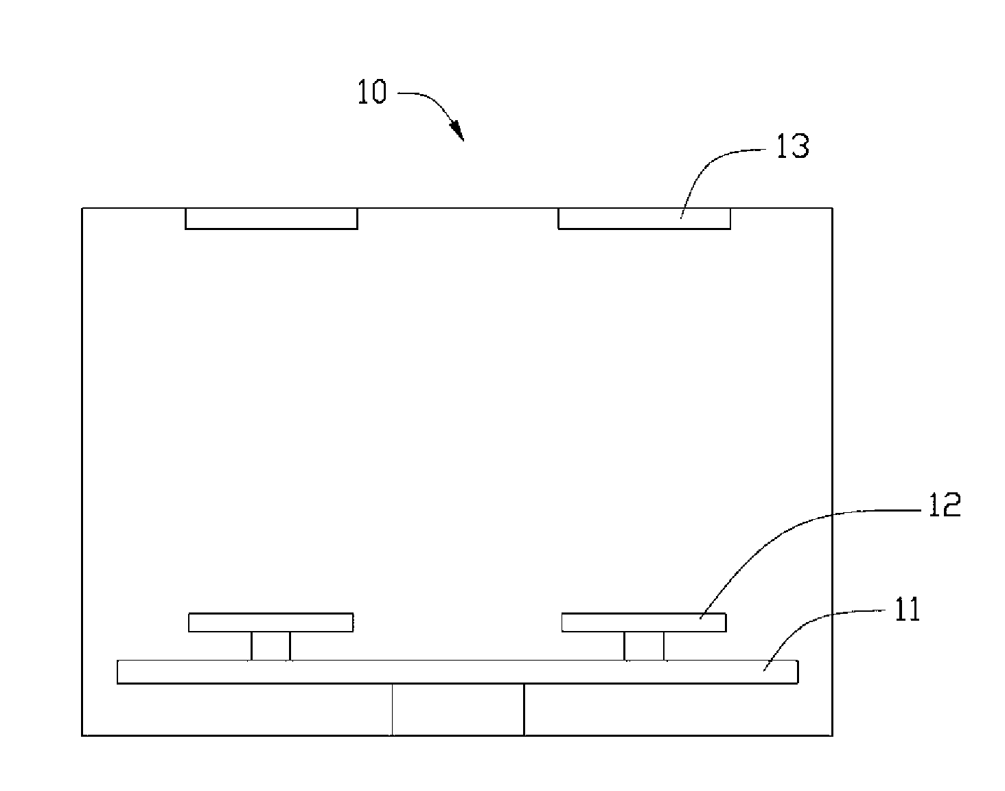
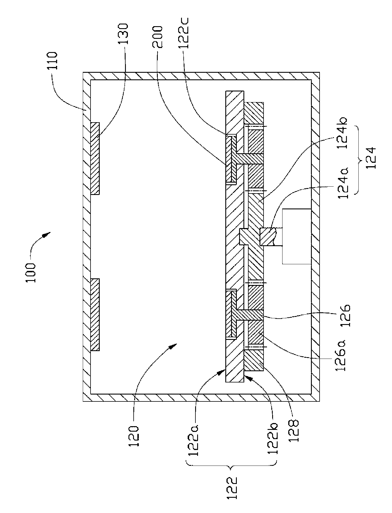
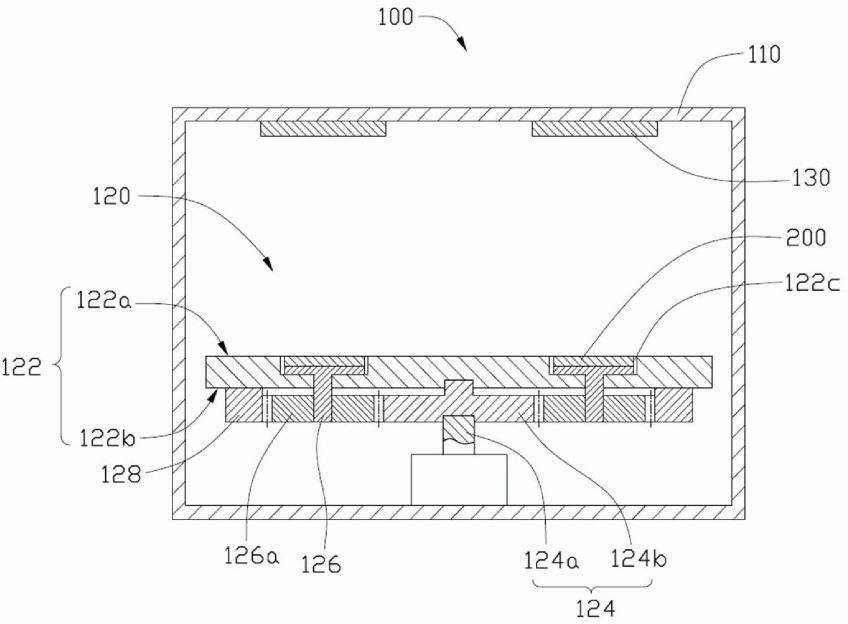
[0009] see figure 2 , a sputtering device 100 provided in a preferred embodiment of the present invention. The sputtering device 100 includes an accommodating cavity 110 , a sputtering turntable 120 , and at least one target 130 . The sputtering turntable 120 is disposed at the inner bottom of the accommodating cavity 110 . The target 130 is disposed on the inside of the top of the accommodating cavity 110 at a certain distance from the sputtering turntable 120 .

[0010] The accommodating cavity 110 is used to form a space for sputtering. The accommodating cavity 110 can be evacuated by a vacuum machine and filled with a suitable gas such as argon. A glow discharge device (not shown in the figure) is also provided in the accommodating cavity 110 to ionize the argon gas filled in the accommodating cavity 110 to generate plasma that can strike the target 130 . In addition, a strong magnetic field can be provided in the accommodating cavity 110 to accelerate the plasma, so t...


PUM


Abstract

The invention relates to a sputtering turntable which comprises a matrix, a driving device and at least one transmission device, wherein the matrix is connected to the driving device, and the transmission device is rotatablely connected to the matrix and is meshed with the driving device; and the matrix comprises an upper surface and a lower surface, the upper surface is provided with at least one groove for containing a base plate to be sputtered, and the depth of the groove ensures that the upper surface of the base plate to be sputtered, which is contained in the groove, can be flush with the upper surface of the matrix. By arranging the groove on the matrix and consequently enabling the upper surface of the base plate to be sputtered in the groove to be flush with the upper surface ofthe matrix, the sputtering turntable avoids uneven sputtering caused by height difference between the surface of the base plate and the surface of the base plate to be sputtered in the sputtering process.

Description

technical field [0001] The invention relates to a turntable device, in particular to a sputtering turntable and a sputtering device using the sputtering turntable. Background technique [0002] Sputtering is a commonly used surface treatment method. It mainly uses glow discharge to make argon (Ar) ions hit the surface of the target, and the atoms of the target are ejected and deposited on the substrate. A thin film forms on the surface. Such as figure 1 A kind of existing sputtering device 10 shown, it mainly comprises a bracket 11, two substrates to be sputtered 12 that are rotatably arranged above the bracket 11, and a plurality of substrates to be sputtered that are arranged on the substrate to be sputtered Target 13 at a certain distance above 12. During the use of the sputtering device 10, an ion region will be formed in the space between the target 13, the bracket 11 and the substrate 12 to be sputtered, and the ions in the ion region fall on the target 13, After t...

Claims


Application Information

Patent Timeline
Patent Type & Authority Applications(China)
IPC IPC(8): C23C14/34
Inventor 黄建豪
Owner HONG FU JIN PRECISION IND (SHENZHEN) CO LTD
Why Eureka
Try Eureka