Supercharge Your Innovation With Domain-Expert AI Agents!

Rollover toilet with annular trap

A water trap and flip-type technology, which is applied in the field of sanitary ware products, can solve the problems of large water trap resistance, large space occupied by the toilet, and easy generation of air pockets, etc., so as to achieve fast and smooth water flow and improve the cleaning effect

Inactive Publication Date: 2010-11-24
王才
View PDF8 Cites 8 Cited by
  • Summary
  • Abstract
  • Description
  • Claims
  • Application Information

AI Technical Summary

Problems solved by technology

[0009] What the present invention aims to solve is the problem that the trap used in the existing traditional toilet has large internal resistance, poor cleaning effect, easy to generate cavitation, and the toilet itself occupies a large space. It provides a toilet with good cleaning effect and water saving performance. Prominent and compact flip-flop toilet with ring trap

Method used


Image

  • Rollover toilet with annular trap
  • Rollover toilet with annular trap
  • Rollover toilet with annular trap

Examples


Embodiment 1

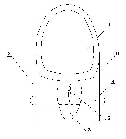
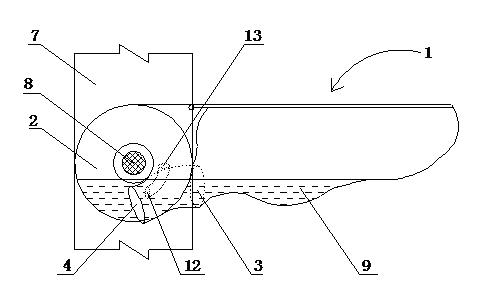
[0033] Embodiment 1: A flip-up toilet with an annular trap, including a toilet body 1, a bracket 7 and a trap 2, the bracket 7 is fixed on the ground, the trap inlet 3 and the sewage outlet at the bottom of the toilet body 1 Connect, trap outlet 4 is connected with sewer through hose, toilet main body 1 is installed on the rotating shaft 8 by a toilet arm 11, rotating shaft 8 is fixed on the support 7, makes toilet main body 1 turn around rotating shaft 8. The water trap 2 is a ring-shaped structure made of hollow pipes. The water trap 2 surrounds the rotating shaft 8 and rotates around the rotating shaft 8 with the toilet main body 1 . The cross-sectional shape of the trap 2 pipe is circular, the diameter of the nozzle from the trap inlet 3 to the trap outlet 4 gradually decreases, and the diameter of the round pipe at the trap outlet 4 is smaller than that at the trap inlet 3 The diameter is 10% smaller, so that the pressure on the liquid flowing through the trap 2 is contin...

Embodiment 2

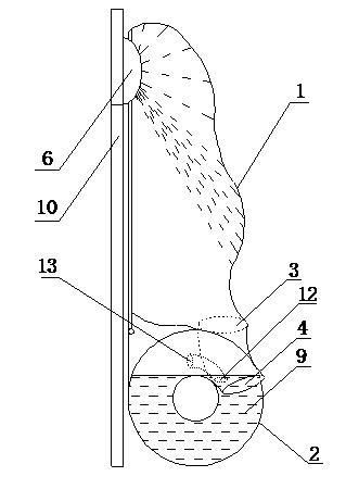
[0036] Embodiment 2: A flip-up toilet with an annular water trap, including a toilet body 1, a bracket 7 and a water trap 2, the bracket is fixed in the wall, the cross-sectional shape of the water trap 2 is oval, and the water trap The diameter of the elliptical tube at the exit 4 of the bend is 5% smaller than the diameter of the elliptical tube at the entrance 3 of the trap, and a section of the entrance 3 of the trap is offset to the right of the trap 2, and the rest are the same as in Example 1. When the toilet is closed, Half of the toilet main body 1 is embedded in the wall 10, reducing the space taken when the toilet is not in use.

Embodiment 3

[0037] Embodiment 3: A flip-up toilet with an annular water trap, including a toilet body 1, a bracket 7 and a water trap 2. The cross-sectional shape of the pipe of the water trap 2 is circular, and the ellipse at the outlet of the water trap 4 The diameter of the pipe is 7% smaller than the diameter of the elliptical pipe at the entrance of the trap 3, and all the others are the same as in Embodiment 1. When the toilet is closed, the toilet main body 1 is close to the wall 10 to reduce the occupied space when the toilet is not in use.


PUM


Abstract

The invention relates to a rollover toilet with an annular trap, in particular to a rollover toilet which has good cleaning effect, outstanding water-saving performance and small occupied area and is provided with an annular trap. The rollover toilet with the annular trap comprises a toilet main body, a support and a trap, wherein the support is fixed on ground or on a wall; an inlet of the trap is connected with a sewage draining outlet at the bottom of the toilet main body, and an outlet of the trap is connected with a sewer through a hose; and the toilet main body is installed on a rotary shaft through a toilet arm, and the rotary shaft is fixed on the support so that the toilet main body can roll over around the rotary shaft. The rollover toilet is characterized in that the trap is in an annular structure and made of a hollow pipe by winding, and the trap is wound around the rotary shaft and rotates along with the rotary shaft of the toilet main body. The rollover toilet with the annular trap has good cleaning effect, outstanding water saving performance and small occupied area.

Description

technical field [0001] The invention relates to the field of sanitary wares, in particular to a flip-type toilet with an annular water trap, which has good cleaning effect, outstanding water-saving performance and small footprint. Background technique [0002] The current flush toilet, whether it is a fixed type or a pull-out or flip-over movable type, relies on the siphon phenomenon generated by the trap to remove the dirt in the toilet, and uses the water retained in the trap to seal the sewer pipe. The rising stench. Among them, the water trap of the fixed toilet is an S-shaped channel, which is arranged at the rear of the toilet and extends backward and upward at an angle of 45 degrees to a certain height to form an upper bend, and then connects downward with the sewer pipe. In order to ensure effective water storage, the lower wall of the upper curved part must be higher than the bottom outlet of the toilet. Although this type of structure can well isolate the floatin...

Claims


Application Information

Patent Timeline
IPC IPC(8): E03D11/12E03D11/18E03D11/02
Inventor 王才
Owner 王才
Features
  • R&D
  • Intellectual Property
  • Life Sciences
  • Materials
  • Tech Scout
  • Unparalleled Data Quality
  • Higher Quality Content
  • 60% Fewer Hallucinations
Learn More