Defect automatic positioning device based on control flow intersection and automatic positioning method thereof

A technology of automatic positioning and control flow, applied in the direction of software testing/debugging, etc., can solve the problems of inconvenience, time-consuming and laborious troubleshooting, low accuracy of positioning defects, etc., to improve the efficiency of troubleshooting, improve the accuracy, and save manpower.

Inactive Publication Date: 2010-11-24
BEIHANG UNIV
View PDF2 Cites 11 Cited by
  • Summary
  • Abstract
  • Description
  • Claims
  • Application Information

AI Technical Summary

Problems solved by technology

[0012] The present invention aims at the problems of time-consuming and labor-intensive troubleshooting, inconvenient troubleshooting, and low accuracy of locating defects ex

Method used


Image

  • Defect automatic positioning device based on control flow intersection and automatic positioning method thereof
  • Defect automatic positioning device based on control flow intersection and automatic positioning method thereof
  • Defect automatic positioning device based on control flow intersection and automatic positioning method thereof

Examples


test Embodiment 2

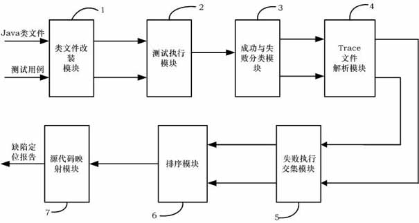
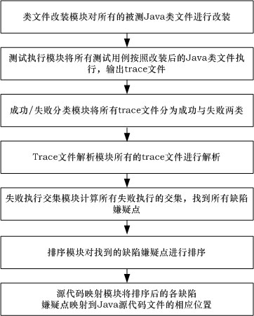
[0055] like Figure 5 As shown in the test cases, the trace files generated by use cases [1], [3], [4] are classified as successful trace files, and the trace files generated by test cases [2], [5], [6] are classified as failed A class of trace files.

[0056] Step 4: Trace file parsing module 4 parses the classified trace files in step 3, so that the parsed trace files can be identified and processed by subsequent modules. All trace information will be organized in a tree structure, where the root node of the tree is the test case information, and the branch and leaf nodes are the three types of program point information in step 1. The trace file generated by each test case is constructed as a corresponding tree data structure storage.

[0057] like Figure 7 As shown in the figure, the trace file generated by the test case [1] is parsed to form a tree structure, where the root node of the tree is the test case [1], and the branch and leaf nodes are the program point infor...

test Embodiment 2

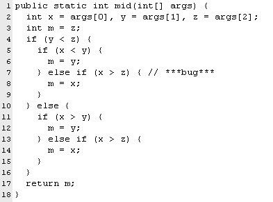
[0060] like Figure 8 As shown, the test cases [2], [5], and [6] are all failed cases, and the intersection of the test cases [2], [5], and [6] is obtained, as Figure 8 All defect suspects shown may contain defects, listed in Figure 8 In the "Suspect Points" column, the defect suspect points are: line 1, line 4, line 5, line 7, and line 14 of the program. It should be noted that the first line is regarded as the entry of the function mid(), and the 14th line is the return statement of the function mid(), both of which are added to the set of defect suspects.

[0061] Step 6: The sorting module 6 sorts the suspected defect points found in step 5 according to their frequency of occurrence in the successfully executed tree structure set from low to high. The numerical value of the frequency is a real number greater than or equal to 0 and less than or equal to 1, defined as: the number of times the defect suspect point appears in the successfully executed tree structure set / th...


PUM


Abstract

The invention discloses a defect automatic positioning device based on control flow intersection and a method thereof. The device comprises a class file modification module, a test execution module, a success/failure sort module, a trace file analysis module, a failure execution intersection module, a sequencing module and a source code mapping module. The method comprises the following steps: the class file modification module modifies the Java class files to be tested; the test execution module executes the test cases to obtain trace files; the success/failure sort module and the trace file analysis module process the trace files; the failure execution intersection module and the sequencing module find out and sequence the defect suspectable points; and finally, the source code mapping module maps the suspectable defects to the corresponding positions of the Java source codes. The method executes the test cases on the modified Java class files, sorts and analyzes the obtained trace files, finds out and sequences the defect suspectable points, and finally maps the defect suspectable points to the corresponding positions of the Java source code files. The invention saves large amounts of human and material resources and enhances the debugging efficiency.

Description

technical field [0001] The invention relates to the field of software testing, in particular to a defect automatic positioning device and an automatic positioning method based on control flow intersection. Background technique [0002] The program defect localization technology is a technology that indicates the cause of abnormal behavior of a defective program. Program defects include program errors (error) and program bugs. The traditional manual defect location technology includes the following basic steps: set breakpoints in the program; execute the program again; check the program status to locate the cause of incorrect output. Obviously, such a defect location method consumes a lot of time, manpower and material resources. And for large-scale programs, it is quite difficult to do such work manually. Therefore, how to locate defects becomes a bottleneck in the program development process. [0003] In the field of automatic defect localization, many different technol...

Claims


Application Information

Patent Timeline
IPC IPC(8): G06F11/36
Inventor 叶钢余丹李重文周家杰马世龙
Owner BEIHANG UNIV
Why Eureka
Try Eureka