Grinding device capable of performing bilateral rotation

A crushing device and two-way rotation technology, which is applied in grain processing and other directions, can solve the problems of large space for crushed objects, excessive crushing, waste of motor power and raw materials for crushed objects, etc.

Inactive Publication Date: 2010-12-01
叶德坚
View PDF0 Cites 11 Cited by
  • Summary
  • Abstract
  • Description
  • Claims
  • Application Information

AI Technical Summary

Problems solved by technology

[0008] 1. The space of the pulverized object hidden in the pulverizer is too large, which will inevitably cause the pulverized object to follow the pulverized blade. It is difficult for the pulverized blade to crush the pulverized object solidly. It needs to rely on high-speed rotation to maintain the pulverized process, and it is easy to produce too much residue. Pulverizes usable residue, thus resulting in excessive waste of motor power and pulverized material
[0009] 2. During the crushing process, some crushed objects have met the crushing requirements, but they cannot be discharged in time. They are not discharged or stopped until they are crushed together with the crushed objects that do not meet the crushing requirements until they meet the crushing requirements. However, they have met the crushing requirements before. The required pulverization is prone to excessive pulverization, so the pulverization speed and uniformity cannot be further improved

Method used


Image

  • Grinding device capable of performing bilateral rotation
  • Grinding device capable of performing bilateral rotation
  • Grinding device capable of performing bilateral rotation

Examples


Embodiment Construction

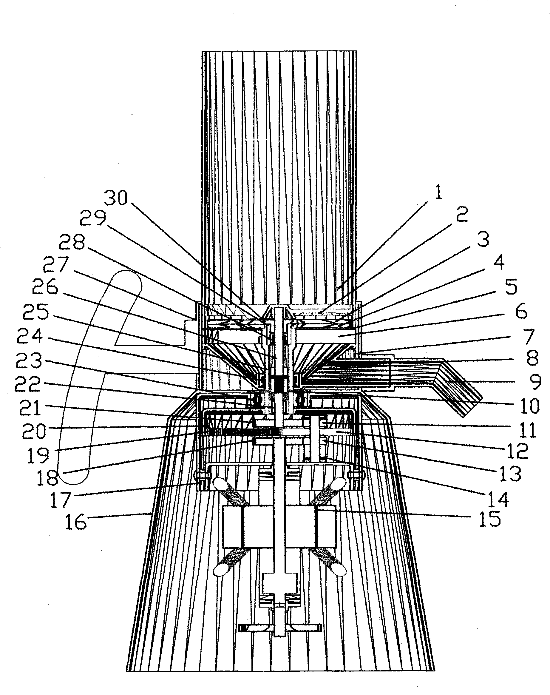
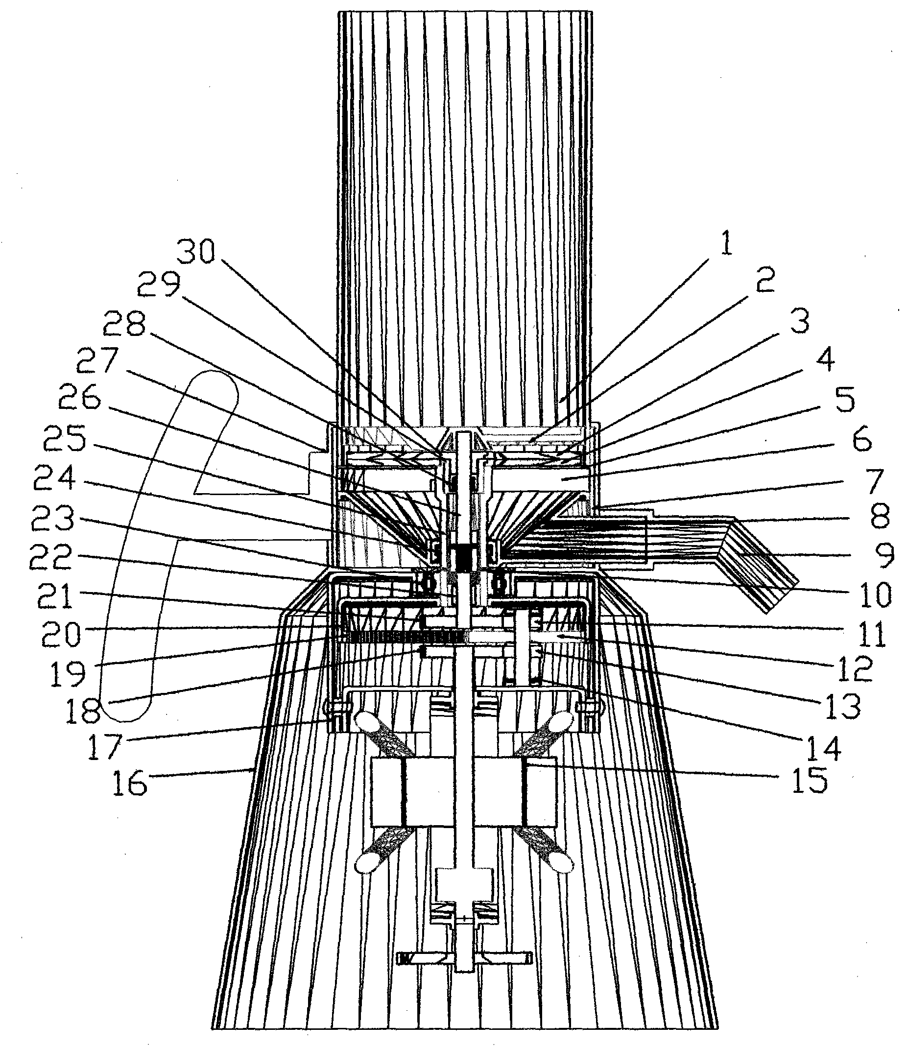
[0024] The following is combined figure 1 and figure 2 To implement this pulverizing device, do a more specific description:

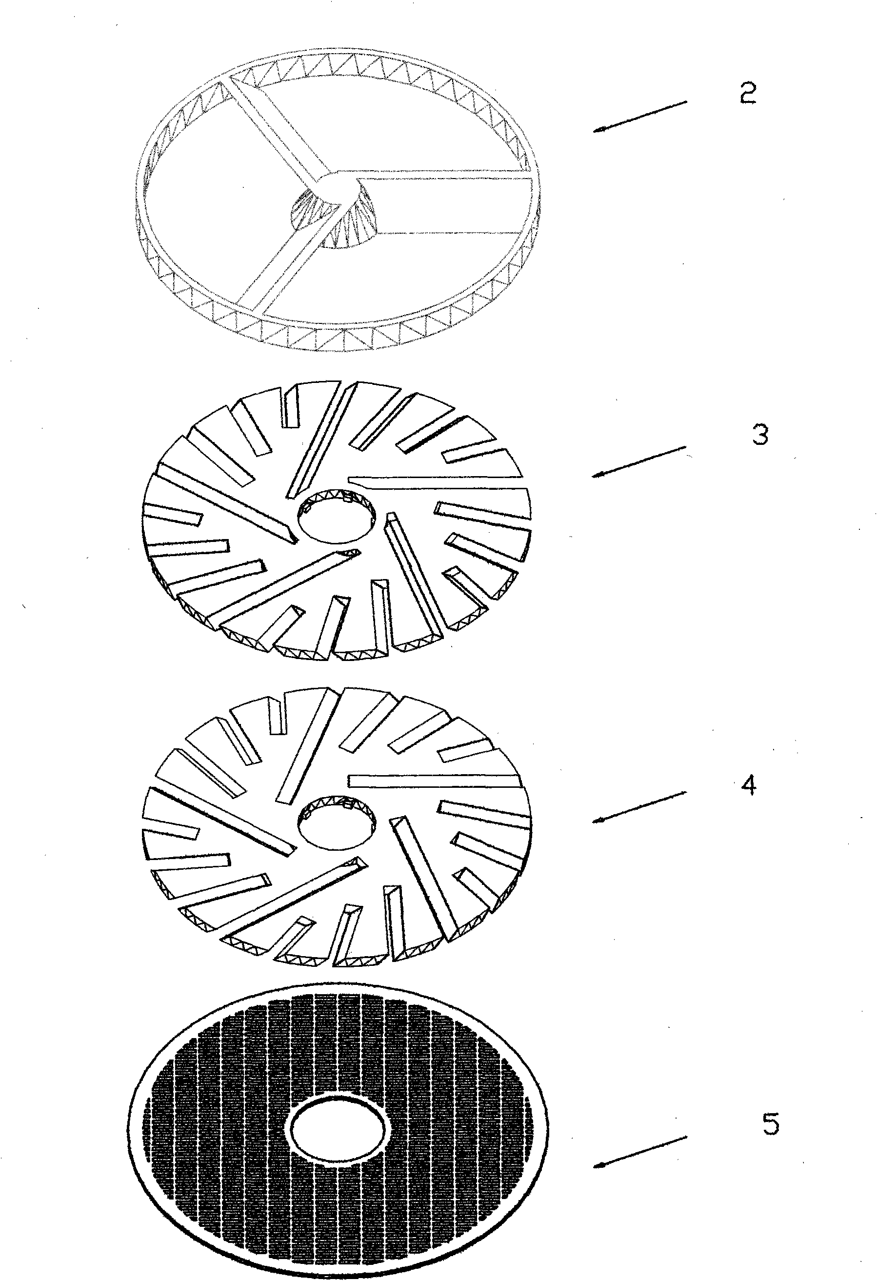
[0025] Such as figure 1 The pulverizer structure provided is a way to implement the pulverizing device, in which the motor, internal gear and five gears, double driving shafts (inner driving shaft and outer driving shaft), double connecting parts (in the cutter wheel A and the inner driving shaft The connecting piece between the shafts and the connecting piece between the cutter wheel B and the external driving shaft) are the driving parts of the pulverizer, which can be installed at the end of the pulverizing device that enters the pulverized material or the end that discharges the pulverized material, so as to apply For horizontal or inverted pulverizers; among them, the fixed material rack, cutter wheel A, cutter wheel B, sieve, sieve support seat, funnel, etc. are the parts that the crushed materials need to pass through, and the installation se...


PUM


Abstract

The invention relates to a grinding device capable of performing bilateral rotation. The grinding device mainly has the following beneficial characteristics and effects: 1) a material-fixing rack is arranged on one end of a cutter wheel A where material to be grinded enters, thus preventing that the material which is not grinded or completely grinded rotates with the cutter wheel A to move and ensuring the material to be grinded enters the cutter groove of the cutter wheel A; 2) two cutter wheels are designed to have cutter grooves with two different inclination directions, thus pressure can be applied to the material to be grinded between the material-fixing rack and a screen to perform solid cyclic grinding and the grindability of each cutter groove can be effectively utilized; 3) the screen is arranged on one end of a cutter wheel B where the grinded material is discharged, the screening speed and discharging speed of the grinded material passing through screen holes are increased owning to the pressure, the grinded material not passing through screen holes can perform cyclic grinding along with the cutter grooves; and 4) by adopting the parts of the grinding device, the grinding space of the grinding cutting tool can be reduced and the devices such as the additional vibrating screen and swinging screen can be eliminated, thus the volume of the grinding machine can be reduced and the residual quantity of the grinded material can be lowered.

Description

Technical field: [0001] The present invention relates to the technical fields of shear pulverization and attrition pulverization. Background technique: [0002] As we all know, cutting or crushing an object with a cutting tool, if the object is not fixed during cutting or crushing, or the object moves with the front direction of the cutting tool, the cutting or crushing ability of the cutting tool to the object will be weakened, but as follows A variety of shredders are: [0003] For example, the existing single-screw pulverizer generally uses the screw and the body part to pulverize the object that can be pulverized (hereinafter referred to as the pulverized object) by means of rotating and scraping. Although the pulverizer in this way can The pulverized object can be crushed under pressure, but as long as there is a distance between the first round of the sharp edge and the second round of the sharp edge of the helical blade, the pulverized object after it is crushed will...

Claims


Application Information

Patent Timeline
Patent Type & Authority Applications(China)
IPC IPC(8): B02C18/06B02C18/22B02C18/18B02C18/16
Inventor 叶德坚
Owner 叶德坚
Why Eureka
Try Eureka