Arrangement structure of copper wires in wire rewinding machine

A technology of wire take-up and copper wire, applied in the field of wire take-up, which can solve the problems of messy wires, increase the cost of downstream customers, storage and transportation of messy wires, etc.

Inactive Publication Date: 2010-12-01
JIANGSU JIACHENG TECH
View PDF7 Cites 1 Cited by
  • Summary
  • Abstract
  • Description
  • Claims
  • Application Information

AI Technical Summary

Problems solved by technology

Therefore, the copper wires on the take-up drum are also arranged horizontally. When disassembling, it is easy to mess up the wires, and it is also easy to mess up the wires during storage and t

Method used


Image

  • Arrangement structure of copper wires in wire rewinding machine
  • Arrangement structure of copper wires in wire rewinding machine
  • Arrangement structure of copper wires in wire rewinding machine

Examples


Embodiment Construction

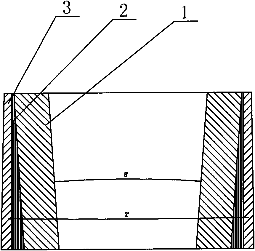
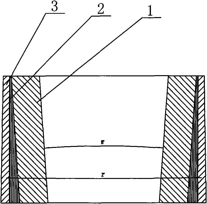
[0012] Such as figure 1 As shown, the arrangement structure of the copper wires in the wire take-up machine includes: an inner wire layer 1 inclined inward with a certain taper, and the vertebra angle of the inner wire layer 1 inclined inward is 6-10 degrees. In this embodiment, The inwardly inclined vertebra angle of the inner thread layer 1 is 8 degrees, the outer thread layer 2 is arranged outside the inner thread layer 1, the outer thread layer 2 is vertically arranged, and the outer thread layer 3 is arranged on the outer side of the inner thread layer 2 The outer thread layer 3 is inclined outward by a certain taper, and the outer thread layer 3 has a taper of 1 to 3 degrees. In this embodiment, the outer thread layer 3 has an outward taper of 2 degrees.

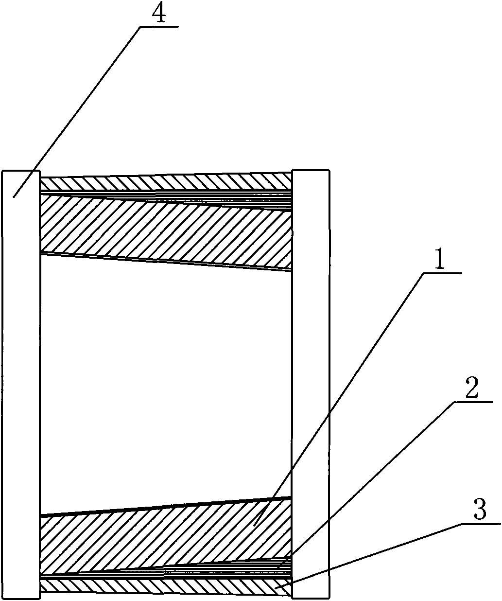
[0013] Such as figure 2 As shown, the copper wires are arranged sequentially on the wire tray 4 through the automatic calculation and control system. The process of arranging the wires is divided into three stages. ...


PUM


Abstract

The invention discloses an arrangement structure of copper wires in a wire rewinding machine. The structure of comprises inner wire layers, wire re-feeding layers and outer wire layers, wherein the inner wire layer tilt inwards for certain conicity; the wire re-feeding layers are arranged outside of the inner wire layers, and the outside of the wire re-feeding layers is vertically arranged; and the outer wire layers are arranged outside of the wire re-feeding layer, and the outer wire layers tilt outwards for certain conicity. The structure has the following advantages: in the unwinding process, the wires can be unwound in the direction of conicity without getting loose; during storage and transportation, the wires can not get loose even if the lower ends of the wires are relatively wide; and in the extracting process, the wires are extracted from the inside, thus being not easy to get loose.

Description

technical field [0001] The invention relates to a wire take-up machine, in particular to an arrangement structure of copper wires in the wire take-up machine. Background technique [0002] When the wire take-up machine is reel-type, the wire reel is needed. The size of the wire reel is generally φ500 or φ630, and the copper capacity of the φ630 reel is about 500Kg. The existing wire reel structure mainly includes: an upper flange, a lower flange fixedly connected to the upper flange through several connecting bolts, a wire take-up barrel is arranged between the upper flange and the lower flange, and the wire take-up The barrel is set horizontally. Therefore, the copper wires on the take-up drum are also arranged horizontally. When disassembling, it is easy to mess up the wires, and it is also easy to mess up the wires during storage and transportation. It must be transported with a special wire drop frame, which increases the cost of downstream customers. When entering the...

Claims


Application Information

Patent Timeline
IPC IPC(8): B65H55/04
Inventor 钱国平张军戴鹏飞
Owner JIANGSU JIACHENG TECH
Why Eureka
Try Eureka