Group directional glass bulb evaporation device

An evaporation and glass bulb technology, which is applied in the field of group directional glass bulb evaporation equipment to achieve the effect of avoiding pollution and high evaporation quality

Inactive Publication Date: 2011-12-28
詹云翔
View PDF5 Cites 0 Cited by
  • Summary
  • Abstract
  • Description
  • Claims
  • Application Information

AI Technical Summary

Problems solved by technology

[0002] Existing aluminum steaming devices for glass bulbs used in various light bulb factories mostly use single aluminum steaming devices with vacuum cup-type long row cars or round row cars. Poor performance, low vacuum degree, easy to produce wrinkled film and demoulding phenomenon, and the speed of aluminum steaming is slow, the qualified rate is also low, there is no corresponding screen outside the heating wire, and due to low vacuum degree, it cannot form uniform and firm coating, and lead to aluminum vapor coating can not be formed at one time and must be followed by the aluminum melting process, not only causing unnecessary damage to the glass bulb, but also causing environmental pollution

Method used


Image

  • Group directional glass bulb evaporation device
  • Group directional glass bulb evaporation device
  • Group directional glass bulb evaporation device

Examples


Embodiment

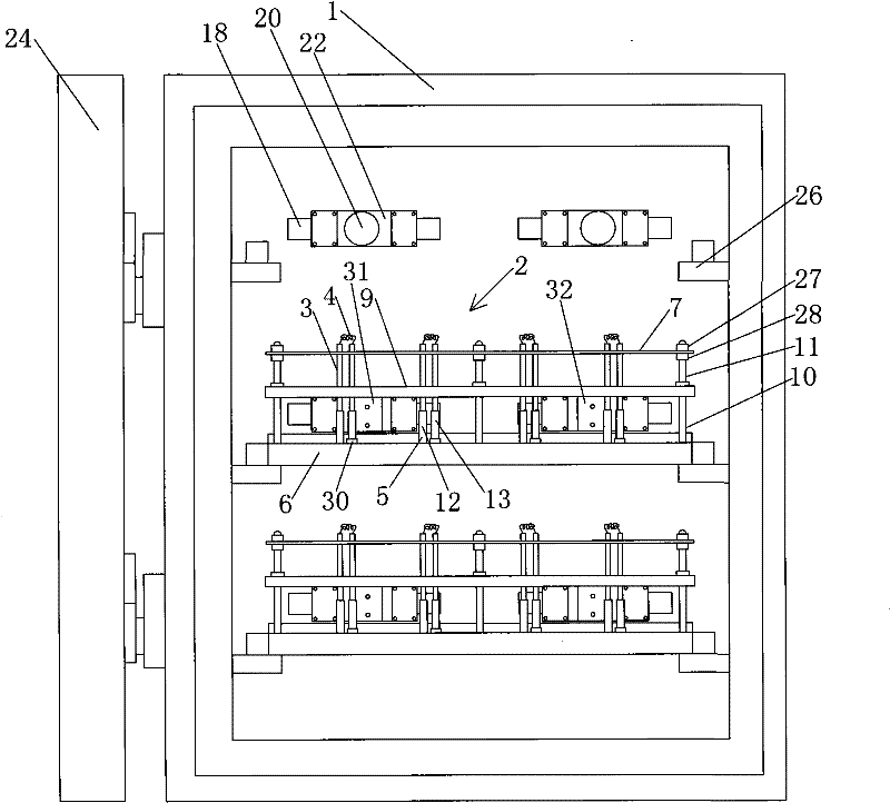
[0026] Example: such as figure 1 As shown, the group oriented glass bulb evaporation equipment includes a vacuum chamber 1 and a door body 24. In the vacuum chamber 1, multi-layer slide rails 26 are arranged from top to bottom, and an evaporation tray is arranged on each layer of slide rails 26. Frame 2, on the evaporation bracket 2, there are many pairs of vertically placed electrode rods 3, the upper ends of the electrode rods 3 are connected with heating wires 4, and a shielding screen (not shown in the figure) is arranged outside the heating wire 4. Regarding the shielding For the specific structure of the screen, please refer to the applicant's invention patent "A glass bulb aluminum evaporation device for vacuum chamber", the patent number is: 93223439.9.

[0027] The overall structure of the evaporation bracket 2 is as follows. It includes a base 6 on which a plurality of connectors 5 are arranged. The lower end of the electrode rod 3 is plugged into the connectors 5. ...


PUM


Abstract

The invention discloses a group directional glass bulb evaporation device, which comprises a vacuum chamber and a door body, wherein a multilayer evaporation bracket is distributed in the vacuum chamber and is distributed with a plurality of pairs of electrode stems which are vertically positioned; the upper end of the electrode stem is connected with a heater strip; a shield is arranged outside the heater strip; the evaporation bracket is provided with a horizontally positioned tray used for placing a glass bulb; the tray is provided with a plurality of through holes; the upper end of the electrode stem and the heater strip pass through the through holes and expose out above the tray; the lower end of the electrode stem is inserted on a plug connector arranged on the base of the evaporation bracket; the plug connector is connected with a battery lead plate at the lateral of the evaporation bracket through a current-carrying plate below the base; the inner wall of the vacuum chamber is correspondingly provided with an electrode block which is connected with a power source; and the electrode plate is contacted with the electrode block. The invention can carry out aluminum evaporation operation on the glass bulb in bulk, has high evaporation quality, is extremely convenient and can avoid the environment pollution.

Description

technical field [0001] The invention relates to an aluminum evaporation equipment for glass bulbs, in particular to a group-oriented glass bulb evaporation equipment which can evaporate aluminum and coat a large number of glass bulbs at one time. Background technique [0002] Most of the existing aluminum steaming devices for glass bulbs used in various light bulb factories use vacuum cup-type long row cars or single aluminum steaming devices with round row cars. Due to poor sealing and low vacuum degree, it is easy to produce wrinkled film and mold release. , and the speed of steaming aluminum is slow, the qualified rate is also low, there is no corresponding screen outside the heating wire, and the vacuum degree is low, etc., it is impossible to form a uniform and firm coating, which leads to the fact that the steamed aluminum coating cannot be formed at one time and must be melted The subsequent processing of the aluminum process not only causes unnecessary damage to the...

Claims


Application Information

Patent Timeline
Patent Type & Authority Patents(China)
IPC IPC(8): C23C14/26C23C14/50
Inventor 詹云翔
Owner 詹云翔
Why Eureka
Try Eureka