Small turbine system in power plant and thermal cycle system in power plant containing same

A technology of thermal cycle system and small steam turbine, which is applied to steam engine installations, machines/engines, and preheating, etc., can solve the problems of reduced power supply efficiency, low cycle efficiency, and reduced plant power consumption in power plants, so as to improve plant power consumption. , The effect of reducing power consumption and improving power supply efficiency

Inactive Publication Date: 2010-12-01
CHINA POWER ENG CONSULTING GRP CORP EAST CHINA ELECTRIC POWER DESIGN INST
View PDF6 Cites 36 Cited by
  • Summary
  • Abstract
  • Description
  • Claims
  • Application Information

AI Technical Summary

Problems solved by technology

but either figure 1 or figure 2 In the system shown, the small steam turbines are all of the condensing type, and the exhaust steam is condensed into condensed water through circulating water (cold source), so that only the working fluid of the exhaust steam can be recovered, but the heat of the exhaust steam (this heat accounts for More than half of the heat of the source steam) will be discharged with the circulating water, so that the entire cycle efficiency is not high
[0005] Moreover, in the above-mentioned traditional condensing small steam turbine drive technology, since the efficiency of the small steam turbine is much lower than that of the main steam turbine, after some large equipment is driven by a small steam turbine instead of an electric motor, it can only reduce the power consumption of the plant. purpose, the power supply efficiency of the entire power plant is reduced

Method used


Image

  • Small turbine system in power plant and thermal cycle system in power plant containing same
  • Small turbine system in power plant and thermal cycle system in power plant containing same
  • Small turbine system in power plant and thermal cycle system in power plant containing same

Examples


Embodiment

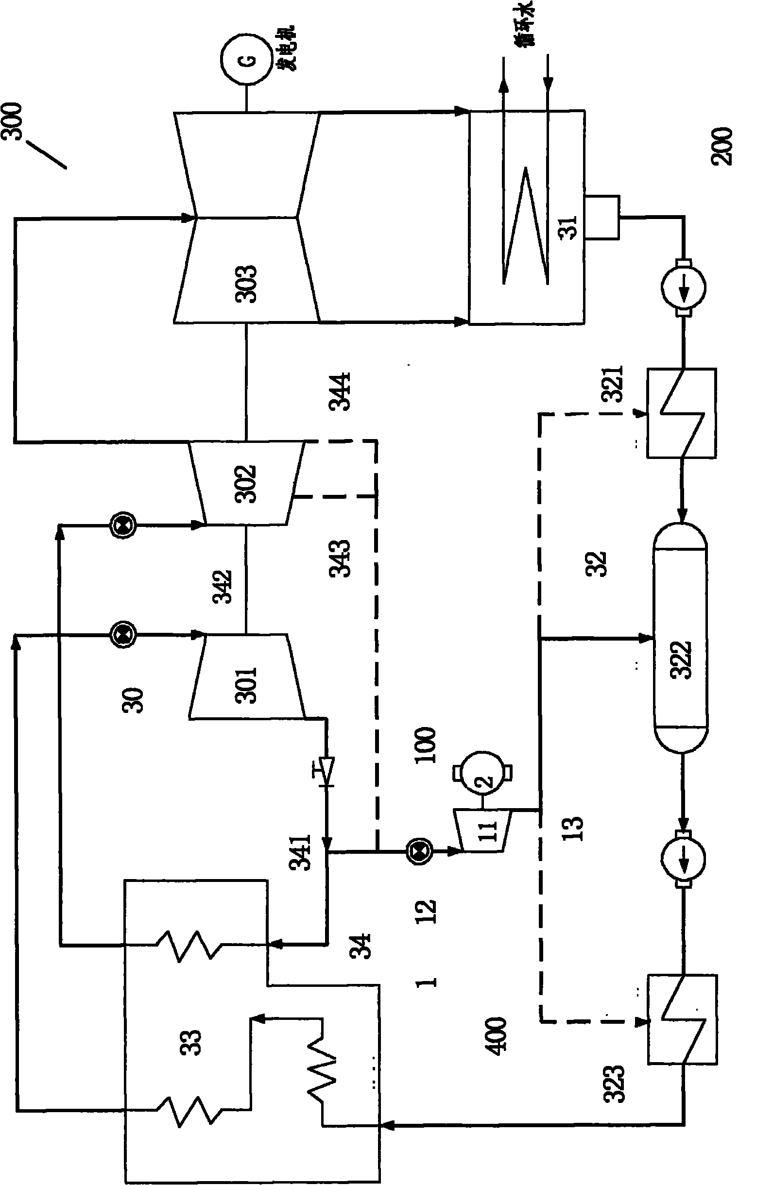
[0101] like image 3 As shown, a specific embodiment of the regenerative small steam turbine system of the power plant of the present invention is shown. Only typical steam sources and heat recovery equipment are connected in the figure, not all possibilities are shown, so image 3 It is used as an illustration only and not as a limitation of the invention.

[0102] image 3 Shown is a power plant regenerative small steam turbine system 100 of the present invention, which is used to recover the heat of the exhaust steam of the small steam turbine 11 to the power plant thermal cycle system 300, which includes: a regenerative small steam turbine unit 1; The regenerative small steam turbine unit 1 includes: a small steam turbine 11; a small steam turbine inlet piping system 12 located at the upstream of the small steam turbine 11, wherein the small steam turbine inlet piping system 12 receives heat from the power plant thermal cycle system 300 steam source 34; and the small st...


PUM


Abstract

The invention provides a small turbine system in a power plant for recovering the exhaust steam heat to the thermal cycle system in the power plant. The system comprises a backheating-type small turbine unit and a driven device driven by the backheating-type small turbine unit. The backheating-type small turbine unit comprises a small turbine, a small turbine admission pipe system and a small turbine exhaust pipe system. The small turbine admission pipe system is arranged on the upstream of the small turbine and receives steam source from the thermal cycle system in the power plant; the small turbine exhaust pipe system is arranged on the downstream of the small turbine; the exhaust steam of the small turbine exhaust pipe system enters to the backheating unit of the thermal cycle system in the power plant so that the exhaust heat is recovered. The invention further provides a backheating system and a thermal cycle system in the power plant containing the small turbine system in the power plant. The systems can greatly improve the power supply efficiency of the unit.

Description

technical field [0001] The invention relates to a power plant system, in particular to a small steam turbine system in a power plant and a thermal cycle system of a power plant containing the system. Background technique [0002] At present, my country's power supply demand is increasing day by day, and the installed capacity is also increasing rapidly year by year. While greatly increasing the parameters of the unit to improve the efficiency of power generation, how to improve the efficiency of power consumption, that is, reduce the power consumption rate of the plant, is getting more and more attention. [0003] At present, the way to greatly reduce the power consumption rate of the plant is mainly to change the large-scale equipment of the power plant from the drive of the electric motor to the drive of the small steam turbine, so that the large-capacity motor can be eliminated, so as to achieve the purpose of greatly reducing the power consumption of the plant. The "smal...

Claims


Application Information

Patent Timeline
Patent Type & Authority Applications(China)
IPC IPC(8): F01K7/32F01K27/00F22B33/18F22D11/00F01K3/00
CPCY02P80/15
Inventor 申松林林磊叶勇健陈晓旭
Owner CHINA POWER ENG CONSULTING GRP CORP EAST CHINA ELECTRIC POWER DESIGN INST
Why Eureka
Try Eureka