[0039] Embodiment one
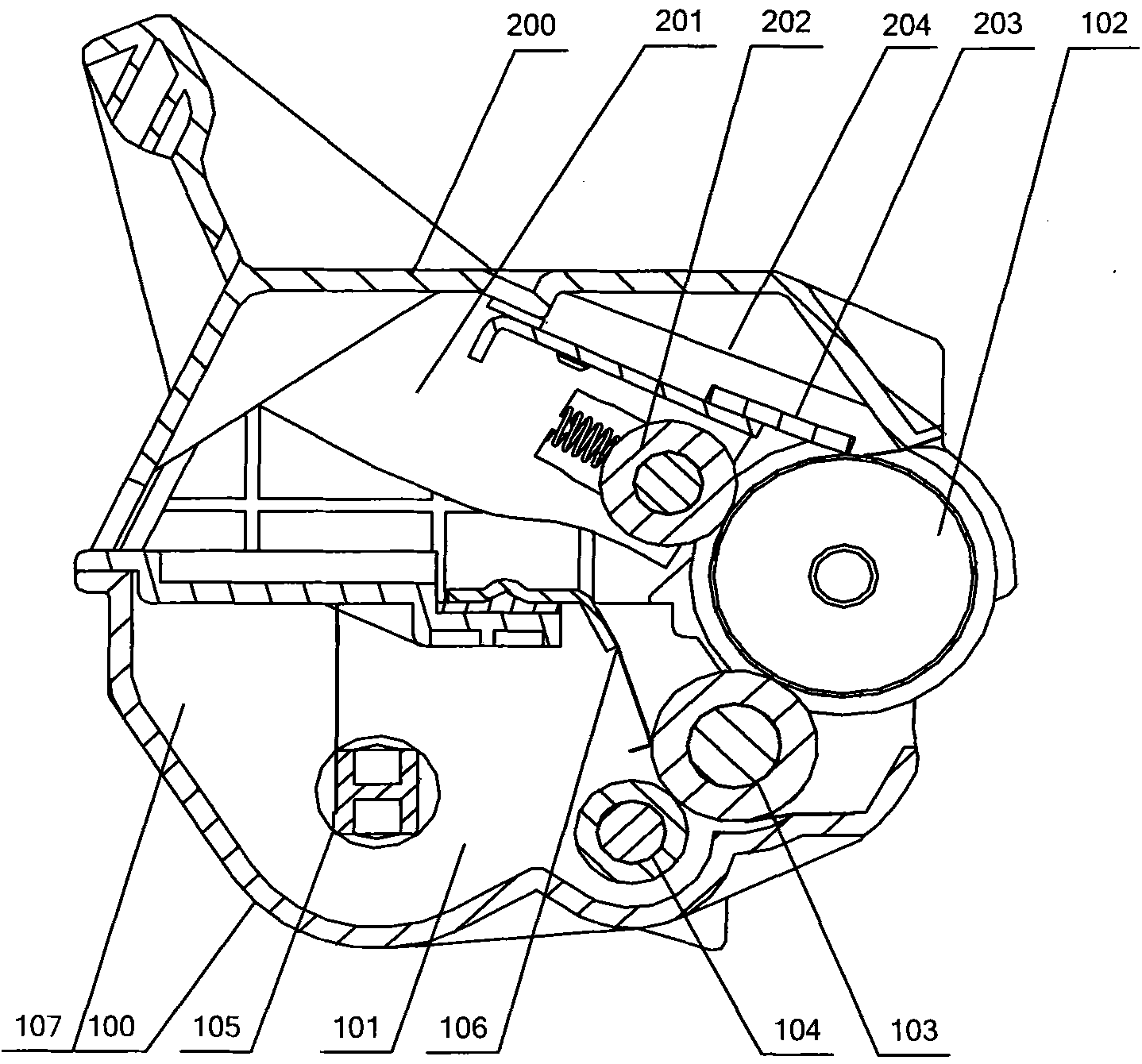
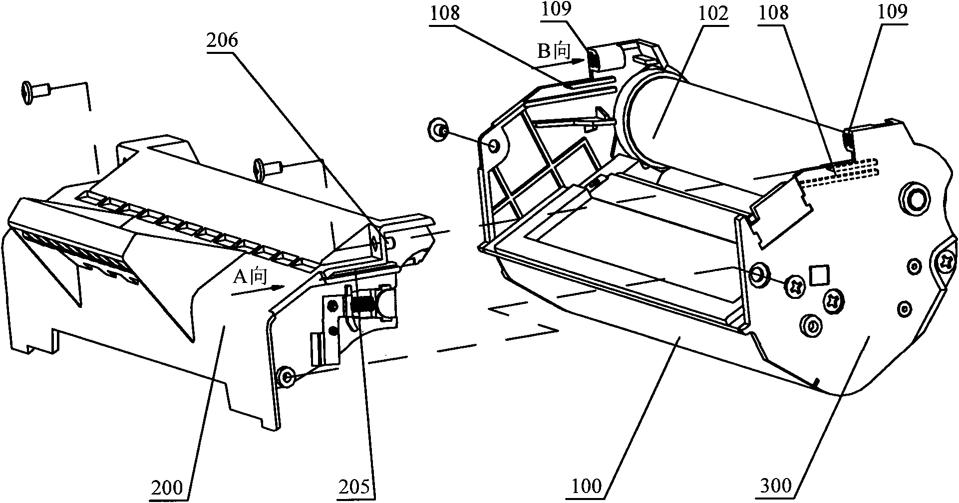
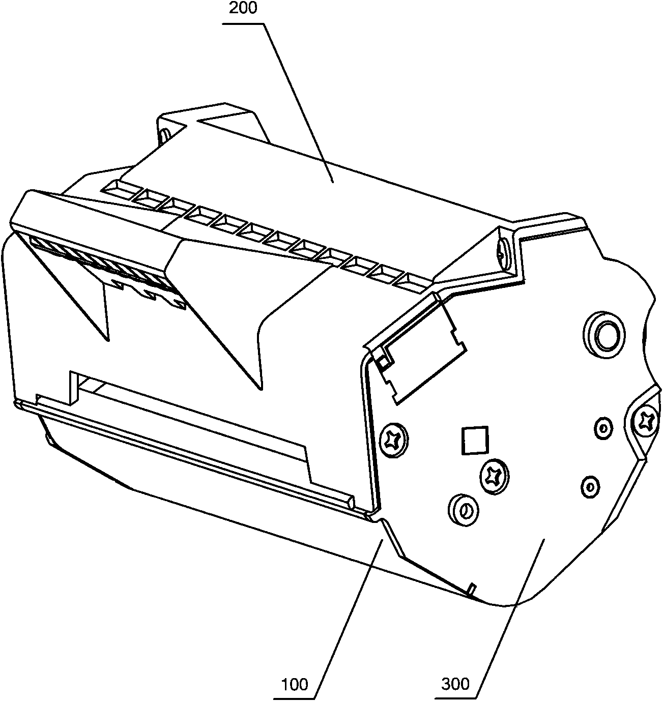
[0040] figure 1 It is a schematic diagram of the side sectional structure of the process box provided by Embodiment 1 of the present invention, figure 2 for figure 1 Schematic diagram of the disassembled state structure of the process box, image 3 for figure 1 Schematic diagram of the assembly state structure of the process box, Figure 4 for figure 1 Schematic diagram of the end cover structure of the middle process box, Figure 5 for figure 1 Schematic diagram of the shell structure of the waste toner bin of the middle process box. In this embodiment, a process box with a typical structure is taken as an example for illustration, as Figure 1-5 As shown, the process cartridge includes a developing chamber casing 100, an end cover 300, a waste toner chamber casing 200, and an imaging device arranged in the developing chamber 101 and the waste toner chamber 201, and the end cap 300 is vertically buckled on the developing chamber casing. The two ends of the body 100 form the main frame, and the two end covers 300 can be fixed with the developing chamber housing 100 by means of screws, pins, welding or hinged joints, and the end covers 300 can also be used to position and support each imaging device.
[0041] like figure 1 As shown, the imaging device in the developing bin 101 includes a photosensitive drum 102 , a developing roller 103 , a powder supply roller 104 , a stirring frame 105 and a powder outlet knife 106 , and the imaging device in the waste toner bin 201 includes a charging roller 202 and a cleaning blade 203 . like figure 1 and Figure 4 As shown, the photosensitive drum 102 is rotatably supported by the pin shaft 301 of the end cover 300, and is in contact with the charging roller 202, and a charging voltage is applied by the charging roller 202, so that the surface of the photosensitive drum 102 is uniformly charged; the laser scanning unit (not shown in the figure ) sends a laser beam carrying image data through the opening of the process box (not shown in the figure), and exposes the surface of the photosensitive drum 102 exposed at the opening of the process box to make its surface potential change to form an electrostatic latent image; The carbon powder in the powder bin part 107 in 101 is transported on the powder supply roller 104 by the stirring frame 105; The powder supply roller 104 supplies the carbon powder to the developing roller 103; The developing roller 103 supplies the carbon powder to the photosensitive drum 102; The toner knife 106 in contact with the surface of the roller 103 controls the amount of toner supplied from the developing roller 103 to the photosensitive drum 102 ; finally a toner image is formed on the surface of the photosensitive drum 102 . During imaging, the transfer roller (not shown in the figure) applies a high voltage to transfer the toner image attached to the photosensitive drum 102 to the printing medium. Residual toner remaining on the photosensitive drum 102 is removed by the cleaning blade 203 . The cleaning blade 203 is located between the transfer roller and the charging roller 202 , and is in contact with the photosensitive drum 102 . A waste toner collection portion 204 in the waste toner box 201 accommodates residual toner that is cleaned from the photosensitive drum 102 by the cleaning blade 203 .
[0042] In the assembled state, the cleaning blade 203 as a cleaning component should be in contact with the surface of the photosensitive drum 102, so that the cleaning blade 203 can scrape off the waste powder on the surface of the photosensitive drum 102 during operation, thereby playing a cleaning role.
[0043] In this embodiment, a guiding and positioning structure is designed on the main frame and the shell of the waste toner bin, which guides and positions the assembly in a simple form, achieves high assembly accuracy, and ensures that the imaging devices can work together well.
[0044]Specifically, the guiding and positioning structure of the process cartridge includes: a guiding assembly and a positioning assembly, and the so-called assembly is composed of at least two parts that cooperate with each other. The guide assembly is separately arranged on the main frame and the waste toner bin shell, and the guide assembly is used to guide the assembly of the main frame and the waste toner bin shell along the first direction; the positioning assembly is separately arranged on the main frame and the waste toner bin shell, and the positioning The components are used for abutting against each other and limiting in the second direction. Wherein, preferably, the second direction and the first direction have an included angle less than 90 degrees and greater than or equal to 0 degrees.
[0045] The above guiding and positioning structure realizes the functions of guiding and positioning respectively during the assembly process, and after realizing accurate positioning, combined with the fast connection between the main frame and the shell of the waste toner bin, the processing box can be made into a stable assembled whole. The advantage of the above structure is that during the assembly process of the main frame and the waste toner bin shell, the guide structure guides the assembly direction between the waste toner bin shell and the main frame along a straight line, avoiding offset and contact, and making The assembly action is simple and easy to operate; on the basis of the guiding structure, the main frame and the waste toner bin shell are positioned through the positioning structure, and then fastened after positioning. The positioning structure makes the assembly process have high positioning accuracy.
[0046] The optimal solution for the assembly process of the process cartridge is that the included angle between the first guiding direction and the second positioning direction is equal to 0 degrees, but in fact, as long as the guiding and positioning with a certain included angle are realized, the process cartridge main frame and waste can be realized. Accurate positioning between powder silo shells.
[0047] This embodiment provides a preferred embodiment of the guiding and positioning structure applied to the assembly of the main frame of the processing box and the shell of the waste toner bin. The guiding assembly is a guiding chute 108 and a guiding rail 205 that are embedded and slid with each other, and the sliding direction is as the first direction, that is figure 2 A direction shown. Specifically, there are two pairs of guide assemblies, which are respectively arranged on opposite surfaces of the ends of the main frame and the waste toner bin housing 200 . As for the main frame, the guide rail 205 can be formed on the end cover 300 or on the developing chamber casing 100 . Furthermore, the surface where the guide assembly is located is perpendicular to the axis of the photosensitive drum 102 and is disposed between the inner wall surface of the end cover 300 and the outer wall surface of the waste toner bin housing 200 . Moreover, the first direction is preferably parallel to the longitudinal section axis of the cleaning blade 203 , that is, the first assembly direction of the main frame and the waste toner box housing 200 is along a direction parallel to the longitudinal section axis of the cleaning blade 203 . In this embodiment, it is designed that the guide chute 108 and the guide rail 205 are parallel to the axis of the longitudinal section of the cleaning blade 203 . During the assembly process of the process cartridge, each position of the blade of the cleaning blade 203 is synchronously close to the surface of the photosensitive drum 102 to ensure that when the waste toner bin housing 200 and the main frame are positioned accurately, the blade of the cleaning blade 203 inside the waste toner bin 201 It is evenly located at the working position where it is in contact with the photosensitive drum 102 .
[0048] In this embodiment, the positioning component is a positioning protrusion 206 and a positioning notch 109 that are matched against each other. figure 2 The B direction shown is actually parallel to the first direction. The number of positioning components is preferably two pairs, which are respectively arranged at the two ends of the process box and formed on the opposite surface of the main frame and the end of the waste toner box housing 200. The part on the main frame can be formed on the end cover 300, It can also be formed on the developing chamber casing 100 . The positioning protrusion 206 and the positioning notch 109 are respectively provided on the downstream end surface and the upstream end surface of the main frame and the waste toner bin housing 200 perpendicular to the assembly direction, and the surface where the positioning component is located and the surface where the guiding component is located are perpendicular to each other. When the positioning protrusion 206 is in contact with the positioning notch 109, the abutment positioning can be realized.
[0049] In this embodiment, if the positioning protrusion 206 and the positioning notch 109 have sufficient insertion length, they can also play a certain guiding role, but it is preferable that the length of the positioning protrusion 206 and the positioning notch 109 is shorter than that of the guide. The guiding stroke of the chute 108 and the guiding slide rail 205, and the positioning assembly is arranged at the end of the guiding stroke of the guiding assembly, and the assembly process is positioned after being guided.
[0050] The assembly process of the process box of the structure shown in this embodiment is divided into two stages, that is, the guiding stage and the positioning stage. The specific process is as follows: first, the guiding chute 108 and the guiding sliding rail 205 are nested and slid to guide the waste powder Assembling direction between the bin housing 200 and the main frame: at the end of the sliding stroke of the guide chute 108 and the guide rail 205, the positioning protrusion 206 and the positioning notch 109 contact and nest with each other until they abut to complete the positioning. In the positioned state, the main frame is fastened to the waste toner bin housing 200 by means of screw connection, pin connection, welding or glue connection. In the above assembly process, the assembly position can be reached under the guidance only by sliding along the first direction, so the assembly process is simple and convenient. The positioning is performed after the guide assembly is completed, which improves the positioning accuracy, can ensure accurate and fast assembly of the process box, and ensure good cooperation between the process box and the imaging device.
[0051] In the present invention, what can play a guiding role is not limited to the chute slide rail shown in the first embodiment, and what can play a positioning role is not limited to the protrusions and notches shown in the first embodiment. First of all, the positions of the guide chute slide rail and the positioning protrusion notch on the main frame and the waste toner bin shell in the first embodiment above can be exchanged without affecting the realization effect. In addition, the guide assembly and the positioning assembly may also use other forms of matching components, and the following describes other preferred implementation forms through embodiments.