

Operating resonant load circuit, dimming circuit and dimming method
A load circuit and resonant technology, applied in the field of operating resonant load circuits, can solve problems such as startup and unsuitable ballasts, and achieve the effect of dimming function
- Summary
- Abstract
- Description
- Claims
- Application Information
AI Technical Summary
Problems solved by technology
Method used
Image

Examples
no. 1 example
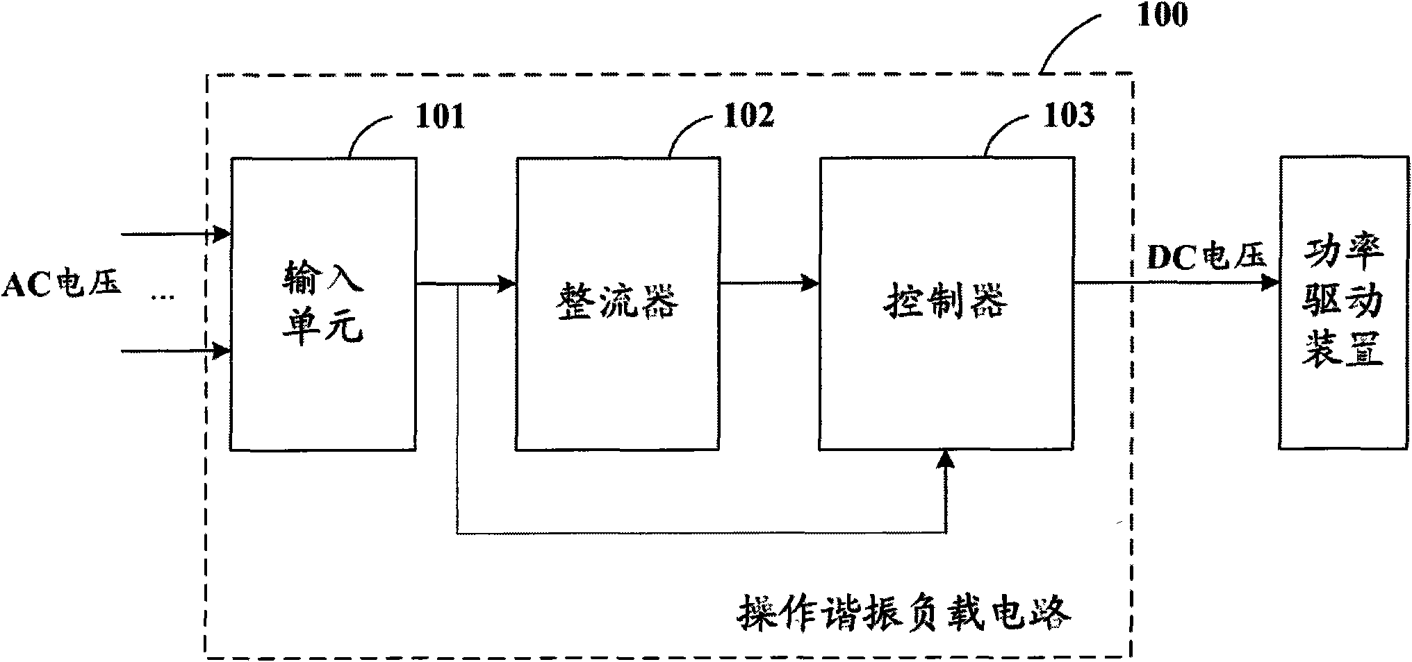
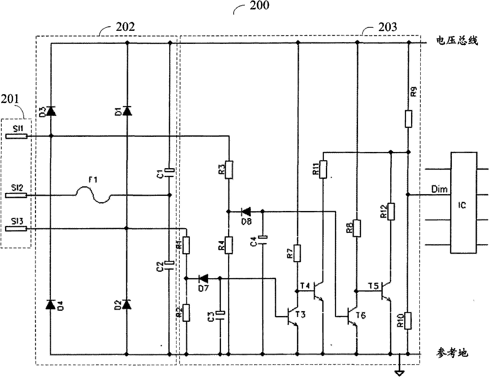
[0028] figure 2 A schematic circuit diagram showing an operating resonant load circuit according to a first embodiment of the present invention. Operation The resonant load circuit 200 operates in conjunction with a three-way switch (not shown) to regulate the power output of the load to three discrete levels corresponding to the three settings of the three-way switch.
[0029] In the operating resonant load circuit 200, SI1, SI2 and SI3 constitute the input unit 201 of the circuit. The three outputs of the traditional three-way switch can be connected to SI1, SI2 and SI3 respectively, so that SI1, SI2 and SI3 can work together in three different ways through the three settings of the three-way switch.
[0030] The first way is to connect SI3 and SI2 to the two output terminals of the AC power supply respectively through the first setting of the three-way switch, and make SI1 idle.
[0031] The second way is to respectively connect SI1 and S12 to the two output ends of the ...
no. 2 example
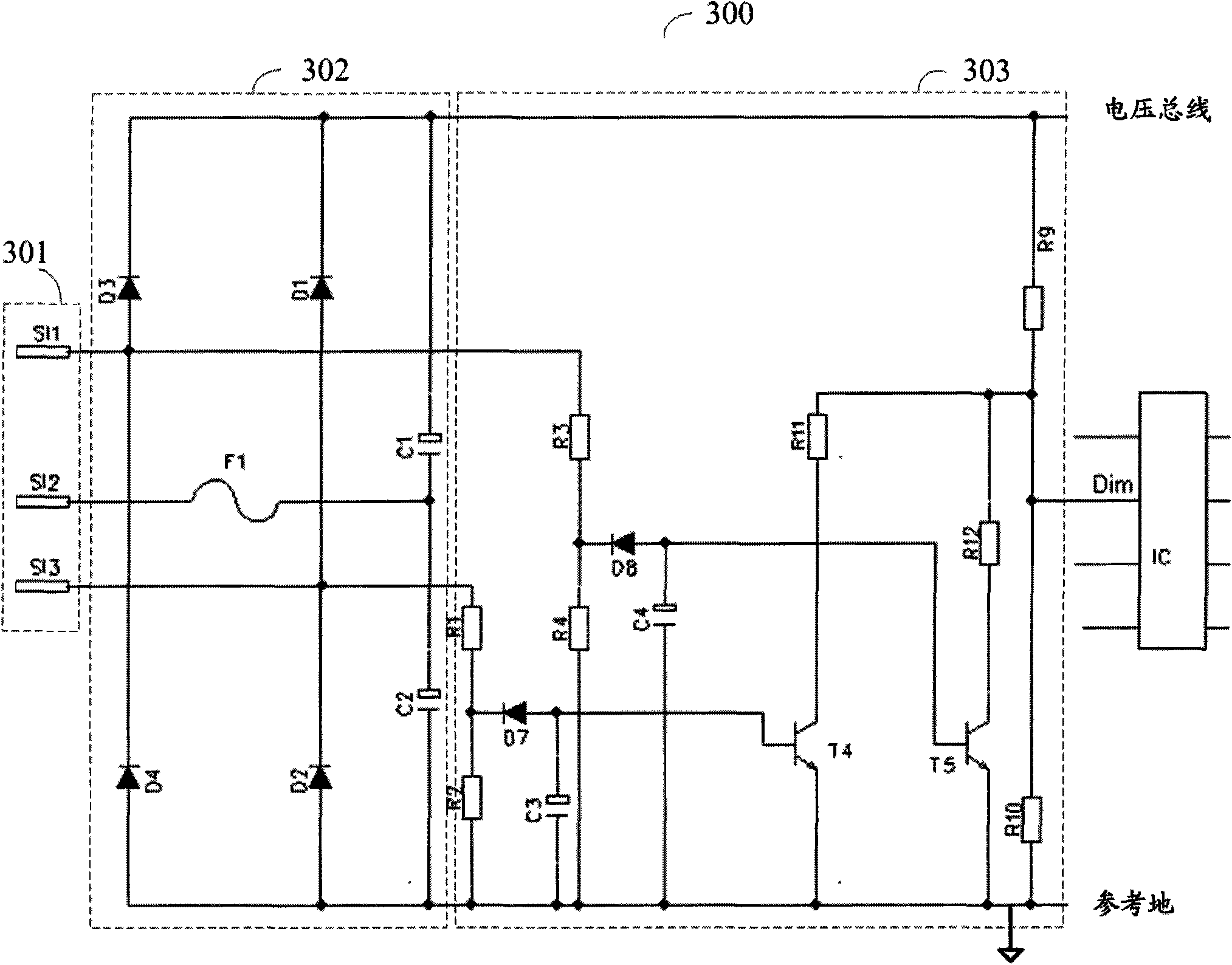
[0053] image 3 A schematic circuit diagram showing an operating resonant load circuit according to a second embodiment of the present invention. Operation The resonant load circuit 300 operates in conjunction with a three-way switch (not shown) to regulate the power output of the load to three discrete levels corresponding to the three settings of the three-way switch.
[0054] In the operating resonant load circuit 300, input terminals SI1, SI2 and SI3 constitute an input unit 301 of the circuit. The three outputs of a conventional three-way switch can be connected to SI1, SI2, and SI3, respectively, so that SI1, SI2, and SI3 can cooperate in three different ways. The three methods mentioned above have been figure 2 It is explained in the description of , and will not be repeated here.
[0055] In operating the resonant load circuit 300, the voltage doubler rectifier 302 has the figure 2 The same structure of the voltage doubler rectifier 202 in the operating resonant ...
no. 3 example
[0076] Figure 4 A schematic circuit diagram showing an operating resonant load circuit according to a third embodiment of the present invention. Operation The resonant load circuit 400 operates in conjunction with a three-way switch (not shown) to regulate the power output of the load to three discrete levels corresponding to the three settings of the three-way switch.
[0077] In the operating resonant load circuit 400, input terminals SI1, SI2 and SI3 constitute an input unit 401 of the circuit. The three outputs of a conventional three-way switch can be connected to SI1, SI2, and SI3, respectively, so that SI1, SI2, and SI3 can cooperate in three different ways. The three methods mentioned above have been figure 2 It is explained in the description of , and will not be repeated here.
[0078] The branch connected in series by transistors D1 and D2, the branch connected in series by transistors D3 and D4, the branch connected in series by transistors D5 and D6, and the ...
PUM
 Abstract
Description
Claims
Application Information