Bubble micro valve and bubble micro valve-based micro-fluidic chip

A microfluidic chip and microvalve technology, which is applied in fluid controllers, valve devices, laboratory containers, etc., can solve the problems of unfavorable use by ordinary users, cumbersome operation, and complicated production technology.

Inactive Publication Date: 2010-12-08
CAPITALBIO CORP +1
View PDF1 Cites 20 Cited by
  • Summary
  • Abstract
  • Description
  • Claims
  • Application Information

AI Technical Summary

Problems solved by technology

[0004] Existing micro valves mainly include pneumatic valves (Science, 2000, 288 (5463): 113-116, Unger M A, Chou H P, Thorsen T, Scherer A, Quake S R.), piezoelectric valves, phase change valves, torque Valves (Lab Chip, 2009, 9, 3511-3516, Chien-Fu Chen, Jikun Liu, Chien-Cheng Chang, Don L.DeVoe), etc. These valves may have complex manufacturing techniques, are difficult to match with portable instruments, or are cumbersome to operate, Not good for normal users

Method used


Image

  • Bubble micro valve and bubble micro valve-based micro-fluidic chip
  • Bubble micro valve and bubble micro valve-based micro-fluidic chip
  • Bubble micro valve and bubble micro valve-based micro-fluidic chip

Examples


Embodiment 1

[0089] Example 1. In a low-humidity environment and an open system, the opening method is external low-humidity air, and the bubble microvalve is opened during the sample addition process, and the generated bubbles block the liquid flow

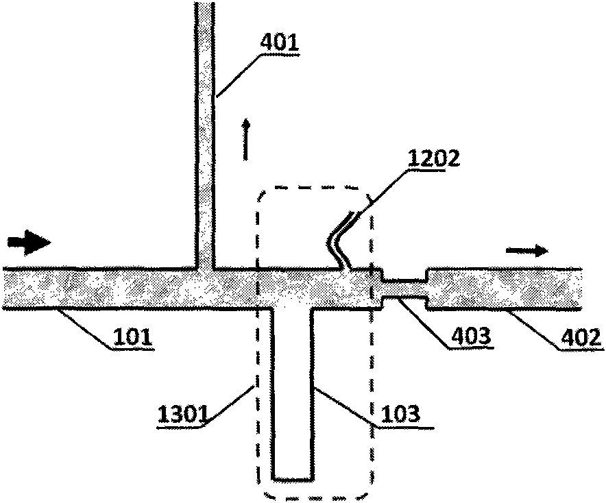
[0090] The chip of this embodiment comprises two layers, the upper layer is a PMMA cover sheet with a thickness of 1mm, and the lower layer is a PMMA bottom sheet with a thickness of 2mm. Such as Figure 4 and Figure 5 As shown, the structure of the upper surface of the bottom film includes a pipeline 101 , a narrow branch pipe 401 communicating with the pipeline 101 , and a wide branch pipe 402 communicating with the pipeline 101 through a barrier pipe 403 . The structure in this embodiment also includes the structure of the bubble microvalve 301 , and the gas pool 103 is directly communicated with the pipeline 101 . The width of pipeline 101 and wide branch pipe 402 is 0.5 mm, the width of narrow branch pipe 401 and blocking pipe 403 is ...

Embodiment 2

[0094] Example 2. In a low-humidity environment, in a closed system, the method of opening the bubble microvalve is a microfluidic chip with external low-humidity air

[0095] Such as Figure 6 As shown, the chip includes two layers, the upper layer is a PMMA cover sheet with a thickness of 1 mm, and the lower layer is a PMMA negative film with a thickness of 2 mm, and a microreactor array is arranged on the upper surface of the lower negative film. Microreactor arrays can be fabricated by existing techniques such as laser engraving, machining or thermocompression sealing. The microreactor array includes a pipeline 101 and 24 reaction pools 302 connected in series through the pipeline 101, and the distance between the reaction pools is equal. In this embodiment, the microreactor array is annular, that is, the pipeline 101 is annular and the reaction pools 302 are also arranged annularly.

[0096] Such as Figure 6 As shown, the microfluidic chip provided by the present inve...

Embodiment 3

[0099] Example 3. In a high-humidity environment, a closed system, and the microfluidic chip when the bubble microvalve is opened by internal low-humidity air

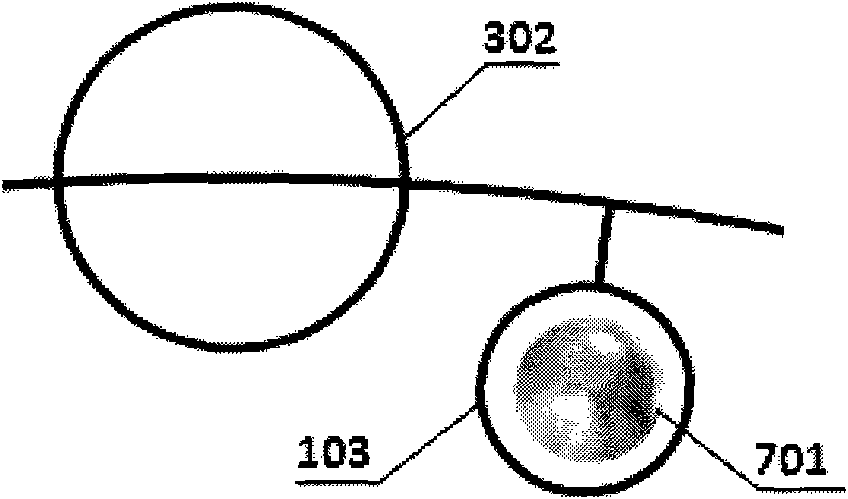
[0100] Such as Figure 7 As shown, the difference between the microfluidic chip of this embodiment and that of Embodiment 2 is that a color-changing silica gel bead 701 is added to the gas cell 103, and the rest of the devices are identical.

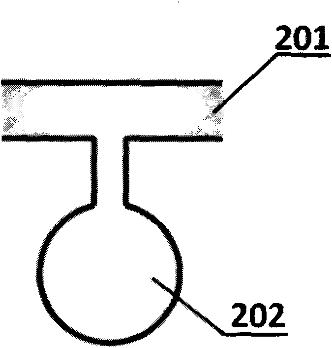
[0101] At a room temperature of 20° C. and a relative humidity of 75%, a color-changing silica gel bead 701 was added to the gas cell 103 , and then the inlet and outlet were closed for 1 hour. Afterwards, the sample inlet and the sample outlet were opened, and a syringe pump was used to add samples to the pipeline 101 at a flow rate of 60 μL / min, and the sample 201 was the PCR system solution. Samples enter each reaction pool in series, and then close the inlet and outlet again. After 3 minutes, if figure 2 As shown, the gas 202 increases in volume and enters the pipeline, fo...


PUM

PropertyMeasurementUnit
lengthaaaaaaaaaa
pore sizeaaaaaaaaaa
heightaaaaaaaaaa

Abstract

The invention discloses a bubble micro valve and a bubble micro valve-based micro-fluidic chip. The bubble micro valve provided by the invention comprises a pipeline, and also comprises at least one gas pool and / or one gas pipe communicated with the pipeline. The bubble micro valve-based micro-fluidic chip belongs to the protection range of the invention. The bubble micro valve provided by the invention has the advantages of simple design, controllable operation, wide application range and efficiency in a non-heating state and a closed system in particular. In the micro-fluidic chip provided by the invention, each micro reactor and the bubble micro valve are arranged at intervals, and the reactors are quickly separated under the action of the bubble micro valve after samples are fed in series to form independent and uniform micro reactor arrays. The method has the advantages that: the samples are fed in series, and the volumes of the samples are uniform; and after chips are fed, the micro reactors are quickly separated in a few minutes, and the micro reactors have no cross contamination.

Description

technical field [0001] The invention relates to the field of microfluidic chips, in particular to a bubble microvalve and a microfluidic chip based on the bubble microvalve. Background technique [0002] Microfluidic chip is based on micro-electromechanical processing technology, which forms a network on the chip by micro-pipelines, and uses controllable micro-fluids to run through the entire system and complete various biological and chemical processes. In the early stage of the development of microfluidic chip technology, chip capillary electrophoresis was the mainstream technology, and the chip used was simple in structure and single in function; Important biological and chemical processes such as reaction and cell lysis have become new hotspots, and in order to study these complex biochemical reactions, it is usually necessary to fabricate a large number of independent and uniform reaction pools on the chip, that is, to construct microreactor arrays. [0003] According ...

Claims


Application Information

Patent Timeline
Patent Type & Authority Applications(China)
IPC IPC(8): C12M1/00G01N33/53
CPCF04B43/00B01L2400/0677B01L2300/1827B01L3/502738F16K99/0019F16K99/0028B01L2400/0633F16K2099/0084F16K99/0044Y10T137/4238B01L2400/0688B01L9/527F16K99/0034B01L2200/027F16K99/0015B01L2200/16B01L2400/0638F16K99/0001
Inventor 张国豪郭素王璨王国青刘淼张锦秀韩蓓邓涛邢婉丽程京
Owner CAPITALBIO CORP
Why Eureka
Try Eureka