Feeding mechanism for vacuum casting furnace

A melting and casting furnace, vacuum technology, applied in the field of improvement of the feeding mechanism of the vacuum melting and casting furnace, can solve the problems of difficult overlapping of material rods, molten steel splashing and burning the smelting chamber, material rod vibration and other problems, so as to improve accuracy and stability, avoid Major equipment accidents, the effect of avoiding swaying and shaking

Active Publication Date: 2010-12-08
AECC AVIATION POWER CO LTD
View PDF5 Cites 6 Cited by
  • Summary
  • Abstract
  • Description
  • Claims
  • Application Information

AI Technical Summary

Problems solved by technology

The disadvantage of the soft link structure is that during the feeding process, the claws of the grabbing mechanism and the rods caught by the claws of the grabbing mechanism will sway and shake, which causes the following two problems: first, during the feeding process , the swaying grabbing mechanism and the material rod caught by the material claw of the grabbing mechanism will collide with the inner wall of the feeding chamber, and the material rod may be shaken off, thereby affecting the accuracy of feeding, and the material rod will be biased and dropped out of the crucible; it may even fall on the crucible and smash the heated crucible, causing the molten steel to splash and burn the melting chamber, causing major equipment accidents
Second: Even if the rod does not slip off, the structure of the feeding device makes it difficult for the axis of the rod to coincide with the axis of the crucible. When feeding, the metal rod weighing about 15 kg will hit the side of the crucible when it is shaking. It may also cause the crucible to break and cause major equipment accidents

Method used


Image

  • Feeding mechanism for vacuum casting furnace
  • Feeding mechanism for vacuum casting furnace
  • Feeding mechanism for vacuum casting furnace

Examples


Embodiment Construction

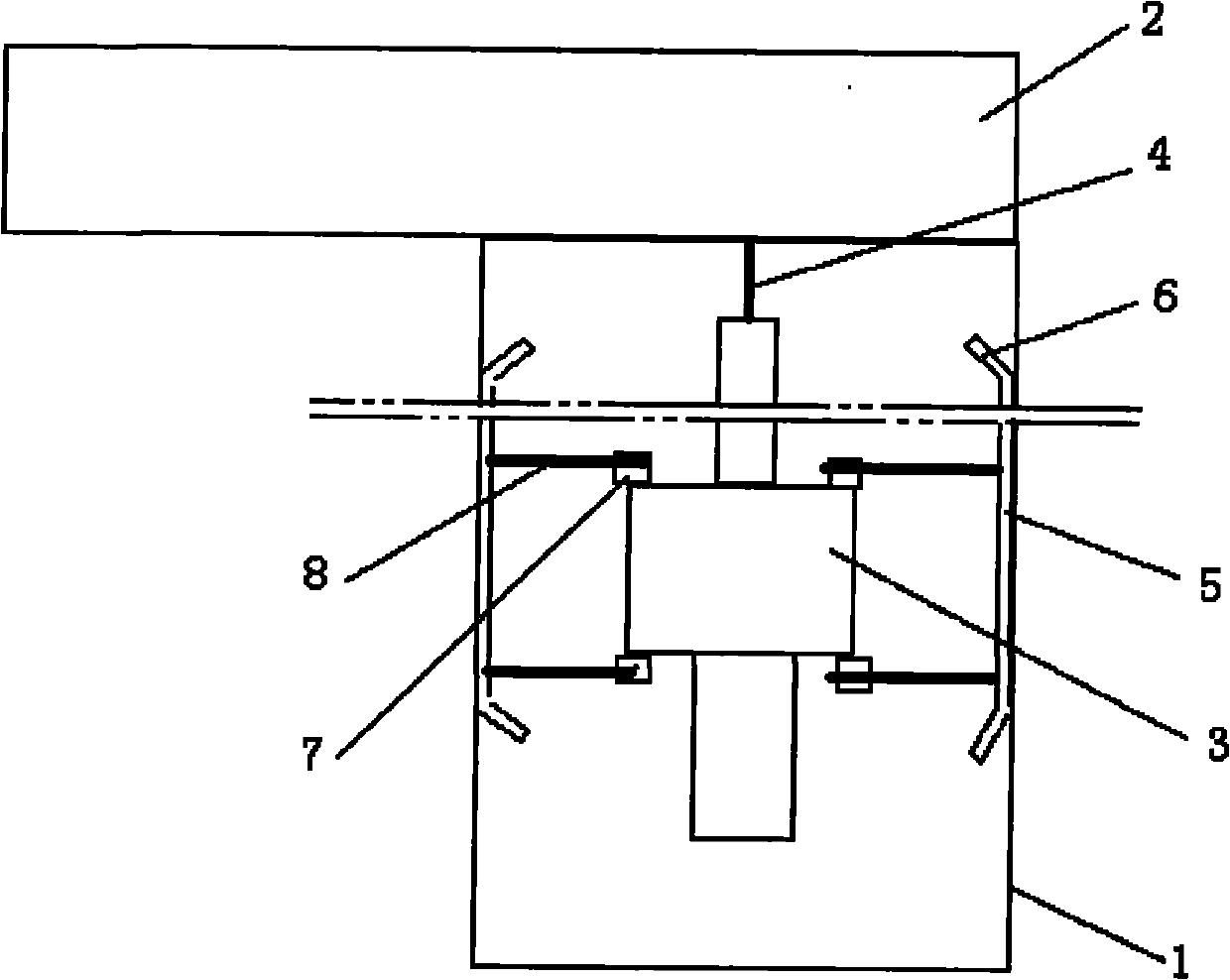
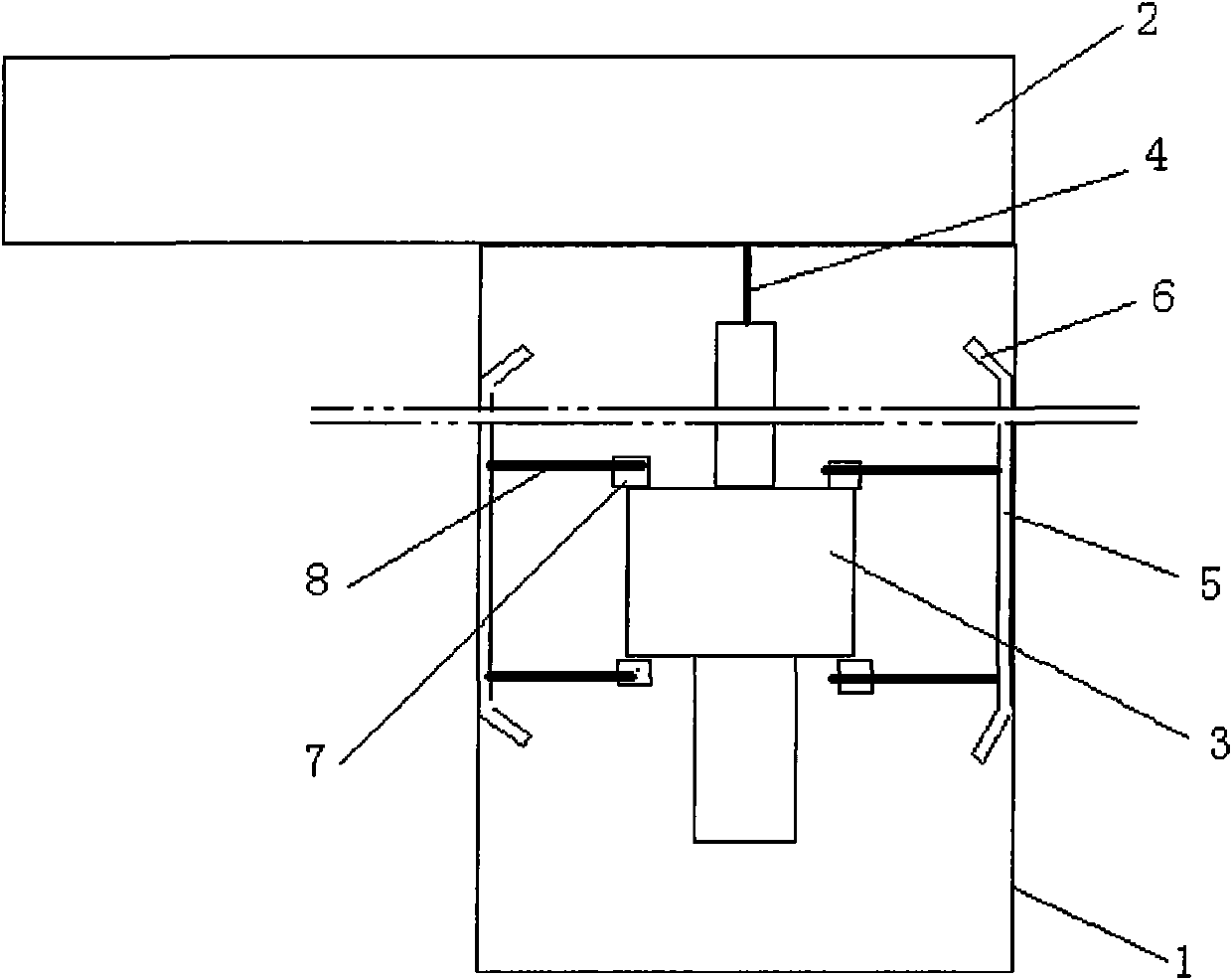
[0008] The present invention will be described in further detail below. see figure 1 , 2 , a vacuum casting furnace feeding device, including a feeding chamber 1 and a driving mechanism 2, the upper end of the circular section shell of the feeding chamber 1 and the right end of the shell of the driving mechanism 2 are connected as a whole through a connecting flange. There is a grabbing mechanism 3 inside the feeding chamber 1, and the grabbing mechanism 3 is composed of an upper connecting rod, a middle cylinder and a lower claw. The upper end of the connecting rod is connected with the lifting mechanism in the driving mechanism 2 by a wire rope or a chain.

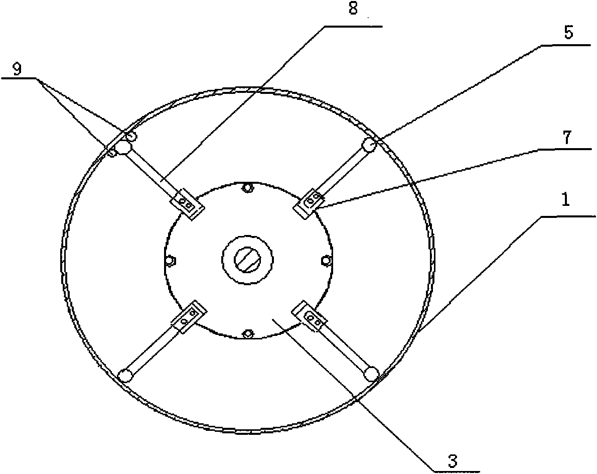
[0009] It is characterized in that there are 3 or 4 guiding mechanisms uniformly distributed along the circumference around the grasping mechanism 3 , and each guiding mechanism is composed of a guiding rod 5 , two connecting pieces 7 and two fixing rods 8 . The guide rod 5 is a circular tube or a round rod, and the a...


PUM


Abstract

The invention belongs to the technology of the design of vacuum casting furnaces and relates to the improvement on a feeding mechanism for a vacuum casting furnace. The feeding mechanism comprises a feeding chamber [1] and a driving mechanism [2] and is characterized in that three or four guide mechanisms with the same structure are uniformly distributed around a material-grasping mechanism [3] along a circumference; and each guide mechanism consists of a guide rod [5], two connecting pieces [7] and two fixing rods [8]. The feeding mechanism has the advantages of preventing the material-grasping mechanism from wobbling and shaking in a feeding process, improving the coaxiality of a charge bar and a crucible, greatly improving the precision and stability of feeding, and avoiding major equipment accidents caused by splashing molten steel resulted from the dropping of the charge bar.

Description

technical field [0001] The invention belongs to the design technology of a vacuum melting and casting furnace, and relates to the improvement of the feeding mechanism of the vacuum melting and casting furnace. Background technique [0002] At present, there are two types of structure for the feeding device of the three-chamber vacuum melting casting furnace in the world. One is the rack and pinion structure. The transmission mode of this structure is to drive the rack through the rotation of the gear to make the material grabbing mechanism move up and down for feeding, which is a rigid connection. Its advantage is that the grabbing mechanism will not shake during the feeding process, but it is limited by the height of the factory building. The other is the chain sprocket structure, which is driven by the rotation of the sprocket to move the chain or wire rope to move the grabbing mechanism up and down to complete the feeding operation. It is a soft connection and has the adv...

Claims


Application Information

Patent Timeline
Patent Type & Authority Applications(China)
IPC IPC(8): F27B14/16
Inventor 赵小林高虹刘永红何成王立娅
Owner AECC AVIATION POWER CO LTD
Why Eureka
Try Eureka