Running instant anti-collision warning system and method

An anti-collision and driving information technology, applied in anti-collision systems and other directions, can solve the problems of unsuitable driving speed, limited signal transmission distance and high cost, and achieve the effect of reducing the probability of collision and improving driving safety.

Active Publication Date: 2010-12-08
AUTOMOTIVE RES & TESTING CENT
0 Cites 39 Cited by

AI-Extracted Technical Summary

Problems solved by technology

Although the electromagnetic wave device has the advantage of being able to scan a long distance, the electromagnetic wave signal used is directional and cannot be used to detect other vehicles in all directions, and the cost is relatively high
The optical device itself has the advantages of a large monitoring range, but it still has the disadvantages of directionality, distance limitation, and high cost.
Although the acoustic device is cheaper than the above two, its signal transmission distance is limited, and it cannot be applied if the driving speed is fast
Most of the mechanical anti-collision devices are additionally installed on the car body as an emergency protection device when a collision occurs, and cannot achieve any pre-prevention effect
[0004] China Taiwan Invention Patent Announcement No. I284297 "Intelligent Real-time Anti-collision Warning System and Method" discloses that a car broadcasts its driving information to the surrounding vehicles, and receives the driving information broadcast...

Abstract

The invention discloses a running instant anti-collision warning system and a running instant anti-collision warning method. The running instant anti-collision warning method comprises the following steps of: continuously sending running information packets of a vehicle outwards by using a wireless communication module of the vehicle and receiving the running information packets broadcasted by other vehicles; determining whether the surrounding vehicles are in an early warning range of the vehicle according to the information of the running information packets; if the surrounding vehicles arein the early warning range of the vehicle, performing coordinate system conversion between the vehicle and other vehicles and carrying out the steps of classifying collision areas to obtain the coordinate positions of collision points, judging whether the collision points exist or not, calculating collision time and the like, wherein the estimation operation of the collision points is not limitedby the positions of the adjacent vehicles. The running instant anti-collision warning system and the running instant anti-collision warning method can judge the potential hazards from all directions and effectively improve the safety by the anti-collision early warning.

Application Domain

Technology Topic

Collision systemReal-time computing +2

Image

  • Running instant anti-collision warning system and method
  • Running instant anti-collision warning system and method
  • Running instant anti-collision warning system and method

Examples

  • Experimental program(1)

Example Embodiment

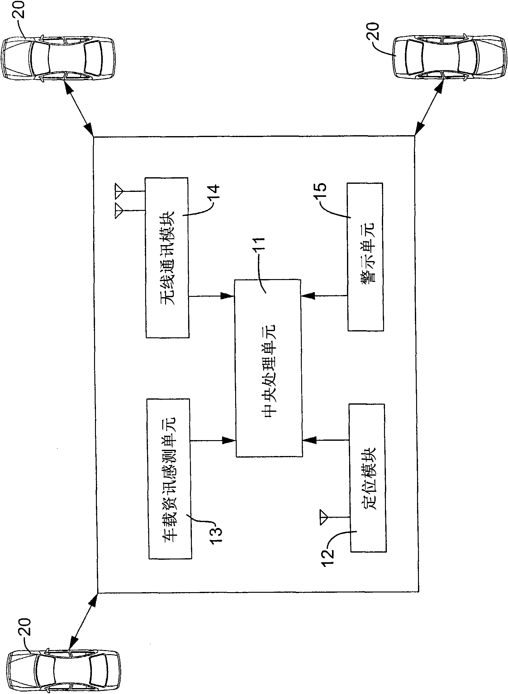
[0039] Please refer to figure 1 As shown, the system of the present invention is integrated in a vehicle, and its basic structure includes:
[0040] A positioning module 12 to locate a vehicle position;
[0041] A central processing unit 11, which receives the position of the vehicle and estimates the speed and heading of the vehicle, and integrates them into a vehicle information packet, and has a built-in anti-collision calculation program and is responsible for data processing and calculation;
[0042] A vehicle information sensing unit 13, which detects and captures various vehicle information of the vehicle and transmits it to the central processing unit 11, such as turn signal, brake status, throttle status, etc.;
[0043] A wireless communication module 14 is connected to the central processing unit 11 and broadcasts the driving information packet sent by the central processing unit 11 to the outside. The driving information packet may include the vehicle position provided by the aforementioned positioning module 12 and the vehicle information sensing unit 13 For vehicle speed, course, vehicle information, etc., the wireless communication module 14 also forms a two-way wireless connection with other vehicle communication modules with the same communication channel (channel) and protocol (protocol), so as to receive traffic information packets from other vehicles and transmit them to the center Processing unit 11;
[0044] A warning unit 15 is connected to the central processing unit 11 and is driven by the central processing unit 11 to issue warning information to remind the driver. The warning information may include graphics, images, sounds, and other formats. In this embodiment, the warning device 15 is A display can provide a collision warning screen to the driver, and cooperate with a sound playback device to output warning audio to inform the driver; the positioning module can be a GPS device, radar device, etc.
[0045] The following takes the positioning module 12 as a GPS device as an example, where the position of the vehicle obtained by the positioning module as described above is also a coordinate obtained by the GPS device:
[0046] When the system of the present invention is activated, the positioning module 12 continuously receives satellite positioning signals, resolves the signals into coordinates, and continuously transmits them to the central processing unit 11. The central processing unit 11 uses the coordinates to estimate the vehicle speed and heading. Integrated into a vehicle driving information packet, the wireless communication module 14 broadcasts the continuously updated vehicle driving information packet to the outside, and also receives the driving information packet broadcasted by other vehicles 20, based on these received vehicle and other vehicles The driving information package determines whether the anti-collision algorithm needs to be executed. The steps include determining whether the surrounding vehicles are within the warning range 201, coordinate system conversion 202, collision area classification 203, determining whether the collision point exists 204, and calculating the longitudinal and lateral collision time 205 and issuing a warning signal 206, etc., which will be explained one by one below.
[0047] Please refer to figure 2 As shown, after receiving the driving information packets of other surrounding vehicles, the central processing unit 11 first determines whether the surrounding vehicles are within the warning range 201, and uses the coordinate information in the driving information packets broadcast by the surrounding vehicles and the coordinate information of the vehicle. Make a comparison to determine whether the surrounding vehicles and the vehicle are close to an early warning range, and it is necessary to calculate whether the two vehicles will collide. If not, it means that the surrounding vehicles and the vehicle are still far enough away, and the calculation is not required for the time being, so it still accepts other Packets of driving information of surrounding vehicles; if yes, proceed to the next step.
[0048] Coordinate system conversion 202 is to convert the coordinate information of the vehicle and other vehicles from spherical coordinates to relative plane coordinates (navigation coordinate system), assuming that the spherical coordinates of the vehicle are (Λ 0 , Λ 0 , H 0 ), the spherical coordinate of the other car is (Λ 1 , Λ 1 , H 1 ), it can be converted as follows:
[0049] x E y E z E = ( N + h ) cos Λ cos λ ( N + h ) cos Λ sin λ [ N ( 1 - e 2 ) + h ] sin Λ , N = a 1 - e 2 sin 2 Λ
[0050] · · · x N y E z D = - cos ( λ 0 ) · sin ( Λ 0 ) - sin ( λ 0 ) · sin ( Λ 0 ) cos ( Λ 0 ) - sin ( λ 0 ) sin ( λ 0 ) 0 - cos ( λ 0 ) · cos ( Λ 0 ) - sin ( λ 0 ) · cos ( Λ 0 ) - sin ( Λ 0 ) X Δp
[0051] among them, Δp = x 1 E - x 0 E y 1 E - y 0 E z 1 E - z 0 E
[0052] The collision area classification 203 is to predict the location of the collision point, the distance between the vehicle and the collision point, and the distance between the other vehicle and the collision point based on the heading angle and coordinates of the vehicle and other information such as the heading angle and coordinates of other vehicles; The heading angle referred to here represents the heading of the vehicle. Please refer to image 3 As shown, first, the codes shown on the drawings are explained as follows:
[0053] B: The current location of the vehicle. The vehicle is driving along the direction D1. The error range of its coordinate position is the range covered by the radius b1.
[0054] A: The current position of the other car. The other car is driving forward along the direction D2. The error range of its coordinate position is the range covered by the radius a1.
[0055] C: The location where the collision point between this vehicle and another vehicle may occur. The error range of the collision point position is the range covered by the radius c1.
[0056] H B : The heading angle of the vehicle is 0 degrees from true north, and the relative included angle between the driving direction D1 of the vehicle and true north is calculated from the clockwise direction, which is a known parameter;
[0057] H A : The heading angle of the other car is based on the 0 degree true north, and the relative included angle between the driving direction D2 of the other car and true north is a known parameter from the clockwise direction;
[0058] H AB :The angle of the other car relative to the car is based on the clockwise direction of the other car’s angle with respect to the car. This H AB The angle value can be calculated based on the coordinate positions of the vehicle and other vehicles.
[0059] H BA : The angle of the vehicle relative to the other vehicle is based on the 0 degree true north and the origin of the other vehicle. Starting from the clockwise direction, the angle of the vehicle to the other vehicle is calculated. This H BA The angle value can be calculated based on the coordinate positions of the vehicle and other vehicles.
[0060] D: The relative straight-line distance between the vehicle and other vehicles is calculated based on the coordinate positions of the vehicle and other vehicles, which is a known parameter.
[0061] The aforementioned three points A, B, and C can form a triangular geometric relationship, and the H A , H BA , H B With H AB The angles are all known, so one of the inner angles ∠CAB (or ∠A) and the other inner angle ∠ABC (or ∠B) can be calculated.
[0062] Please refer to Figure 4A to Figure 5B As shown, if the position of the vehicle is taken as the origin (represented by a single dot on the drawing), the position of the other vehicle (represented by a double dot) can be relatively located in quadrants I to IV. If the parking space is in quadrants I and IV, the calculation formula for angles ∠A and ∠B includes aspect I to IV. If the other car is in quadrants II and III, the calculation formula for angles ∠A and ∠B Contains aspect V to aspect VIII, and the calculation formulas are organized into the following two tables.
[0063] angle
[0064] Table 1: The collision point is in quadrants I and IV
[0065] angle
[0066] Table 2: The collision point is in the second and third quadrants
[0067] Among the aforementioned eight modes, only one of the modes can obtain the correct calculation result that both ∠A and ∠B are both positive and less than 180°, which means that there is a collision point between car A and car B; However, if any of the angle values ​​is negative or greater than 180°, it is an error, which means that there is no collision point between car A and car B.
[0068] Please come back again image 3 As shown, for a triangle composed of three points A, B, and C, when ∠A and ∠B are calculated, the value of the collision angle ∠C can be obtained, and the linear distance D between the two points A and B is also If it is known, the required distance data BDM and ADM can be calculated using the law of sine:
[0069] ∠ A BDM = ∠ B ADM = ∠ C D
[0070] Among them, BDM represents the distance between the vehicle position B and the collision point C. In addition, ADM indicates the distance between the position A of the other car and the collision point C.
[0071] Please come back figure 2 As shown, when the distance values ​​ADM and BDM have been calculated, proceed to the next step: determine whether the collision point exists 204, which is determined based on the following two conditions, namely the position vector between the vehicle and the collision point Direction angle and the driving direction of the vehicle H B Determine whether it is in the same direction, and the position vector of the other car and the collision point The direction angle and the driving direction of other cars H A Whether the same direction; such as Figure 6A As shown, if the vector Direction angle and driving direction H A (As indicated by the dotted arrow) are in the same direction, and the vector Direction angle and driving direction H B Also in the same direction, it means that the collision point C is present and proceed to the next step; otherwise, if any of the conditions are not established, it means that the collision point does not exist, for example Figure 6B As shown, assuming the vector Direction angle and driving direction H A (As indicated by the dotted arrow) is the reverse direction, which means that the other car has moved away from point C to point A. Even if the car is moving from point B to point C, a collision is still impossible, so it is impossible to cause a collision accident.
[0072] Calculate the collision time 205. In the step of calculating the collision time, it is divided into the longitudinal collision time and the lateral collision time; the longitudinal collision time is based on the speed of the other car V A The distance ADM from the collision point C finds the required time t to reach the collision point C ADM , And the speed of the vehicle V B The distance from the collision point C BDM to find the required time t to reach the collision point C BDM , The calculation formula of the two is as follows:
[0073]
[0074]
[0075] Please refer to Figure 7A As shown, at calculation time t ADM Error range can be added when image 3 The radius of the error range shown above is a1, so a period of time t can be obtained A1~A2 , The same time t can be obtained in this vehicle B1~B2 , If the two times have an overlapping period, it represents the time when the two vehicles may collide, for example, 4-6 seconds and 5-7 seconds have overlapping periods;
[0076] Please refer to Figure 7B As shown, if time t A1~A2 With t B1~B2 If there is no overlapping period, it means that there will be no collision;
[0077] For the judgment of the so-called lateral collision time, please refer to Figure 8 As shown, it means that if the two vehicles continue to move forward, before they reach the collision point, the two sides may have a lateral collision accident due to their large body (such as large container trucks, connected vehicles, etc.). Therefore, the present invention is based on the speed of both parties. Projection amount to calculate a lateral collision time t LSM , The calculation formula is as follows:
[0078] t LSM = D V A · cos ( ∠ A ) + V B · cos ( ∠ B )
[0079] When the lateral collision time is less than a preset value, a warning will be issued to remind the driver.
[0080] Warning signal 206, please refer to Picture 9 As shown, after calculating the longitudinal and lateral collision time, the present invention can generate a warning signal through the warning unit 15. In this embodiment, the warning device 15 displays a collision warning screen to the driver, with the vehicle as the origin on the screen , Display other car position 31, collision position 30 longitudinal, lateral collision time and other information.

PUM

no PUM

Description & Claims & Application Information

We can also present the details of the Description, Claims and Application information to help users get a comprehensive understanding of the technical details of the patent, such as background art, summary of invention, brief description of drawings, description of embodiments, and other original content. On the other hand, users can also determine the specific scope of protection of the technology through the list of claims; as well as understand the changes in the life cycle of the technology with the presentation of the patent timeline. Login to view more.

Similar technology patents

Method for preparing scandium-zirconium powder through spray pyrolysis and scandium-zirconium powder prepared through method

InactiveCN111205095AReduce the chance of collisionShort collision timeFinal product manufactureFuel cellsSolvent evaporationScandium
Owner:CHINA ENFI ENGINEERING CORPORATION

Anti-collision buffering equipment for highway engineering maintenance

PendingCN114250729AQuick and easy recyclingReduce the chance of collisionTraffic signalsRoad signsSpeed bumpEquipment use
Owner:GUIZHOU TRANSPORTATION PLANNING SURVEY & DESIGN ACADEME

Non-return structure of manual pump

InactiveCN103670994AReduce the chance of collisionReduced impact wearPositive displacement pump componentsPiston pumpsChromiumEngineering
Owner:南通高盛机械制造有限公司

Table tennis picking device and control method thereof

PendingCN111282234AReduce labor costsReduce the chance of collisionBall sportsStructural engineeringMechanical equipment
Owner:JIANGSU UNIVERSITY OF TECHNOLOGY

Classification and recommendation of technical efficacy words

  • Reduce the chance of collision
  • Improve driving safety

Indoor positioning method based on UWB technology

InactiveCN106211310AReduce the chance of collisionAvoid data receptionSynchronisation arrangementCollision probabilityAloha
Owner:BEIJING YONGANXINTONG TECH CO LTD

Dry-grinding diamond grinding wheel

ActiveCN105215866ATimely exclusionReduce the chance of collisionBonded abrasive wheelsGrinding devicesDiamond grindingBuilding material
Owner:JIANGSU FENGTAI TOOLS

RTS/CTS starting method and device

ActiveCN103916972AImprove rationalityReduce the chance of collisionNetwork topologiesCollision probabilityDistributed computing
Owner:CHINA MOBILE COMM GRP CO LTD

Active anti-dazzle method and vehicle active anti-dazzle device

PendingCN106985640AReduce the incidence of traffic accidentsImprove driving safetyWindowsAntiglare equipmentTransmittanceLiquid crystal
Owner:HASCO VISION TECHNOLOGY CO LTD
Why Eureka
Try Eureka