Cavity filter

A cavity filter and cavity technology, applied in the field of communication, can solve problems such as easy aging and poor waterproof performance

Inactive Publication Date: 2010-12-08
ANHUI TATFOOK TECH CO LTD
View PDF4 Cites 10 Cited by
  • Summary
  • Abstract
  • Description
  • Claims
  • Application Information

AI Technical Summary

Problems solved by technology

However, the apron is in the wild environment and is pro

Method used


Image

  • Cavity filter
  • Cavity filter
  • Cavity filter

Examples


Embodiment Construction

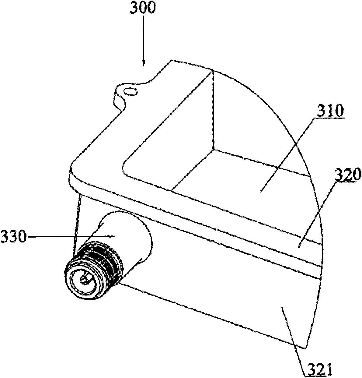
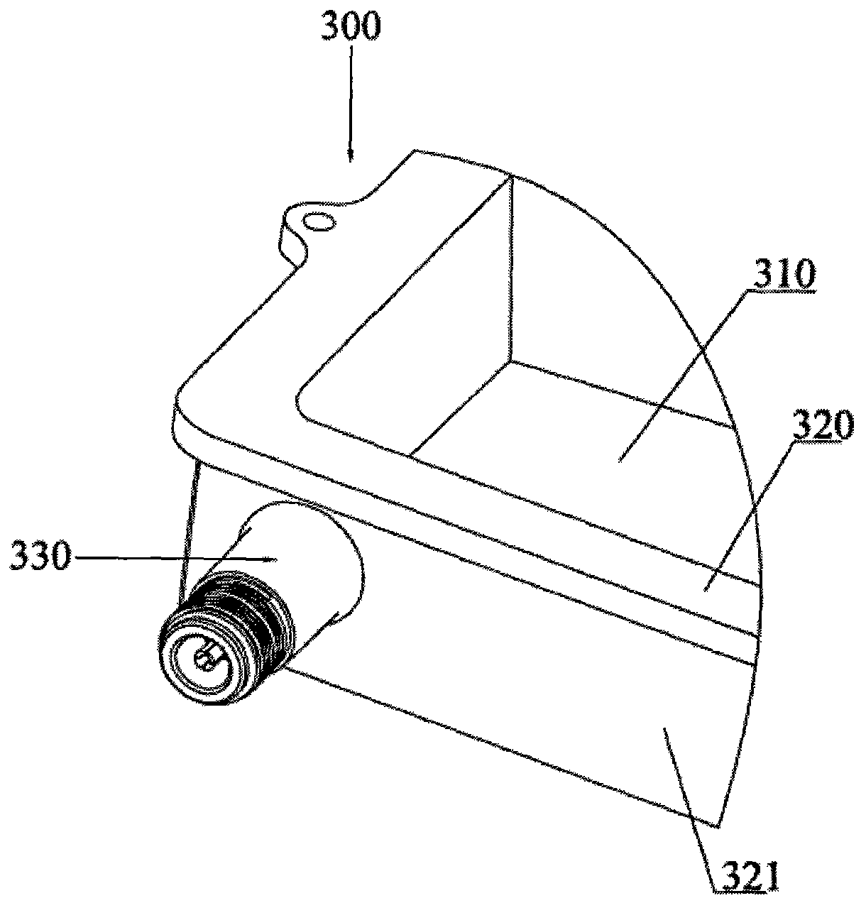
[0015] see figure 2 , the cavity filter 300 includes a cavity 320 and a connector 330 . A cavity 310 is formed on the cavity body 320 . The connector 330 is used to connect with the antenna of the base station system.

[0016] The cavity 320 includes a sidewall 321 . The connector 330 is cylindrical and hollow inside, and is arranged on the side wall 321, and the connection between the side wall 321 and the connector 330 is provided with a perforation (not shown in the figure), the perforation and the connector The hollows of 330 together form a unified hollow for assembling the connector assembly. The end of the connector 330 away from the cavity 320 is provided with threads for combining with the antenna. The cavity 320 and the connector 330 are integrally formed, so that the waterproof performance of the cavity filter 300 is better than the traditional implementation method of separately installing the connector on the cavity filter.

[0017] The integrated cavity 320...


PUM


Abstract

The invention relates to the technical field of communication, in particular to a cavity filter. The cavity filter comprises a cavity and a connector, wherein the connector and the cavity are integrated into a whole so as to ensure that the water proofing of the cavity filter is better. Meanwhile, Compared with a traditional implementation mode that the connector is fixed on a shell through a bolt, the invention reduces mounting procedures, saves time and labor power, and is beneficial to improving the production efficiency in scale production.

Description

technical field [0001] The invention relates to the technical field of communications, in particular to a cavity filter. Background technique [0002] As a frequency selection device, filters are widely used in the field of communication, especially in the field of radio frequency communication. In the base station where the communication system completes signal transmission and reception, the filter is used to select the communication signal and filter out the clutter or interference signal outside the frequency of the communication signal. [0003] At present, in mobile communication base station systems, cavity filters are commonly used to select frequencies for signals transmitted and received by antennas. Therefore, a connector for transmitting signals is usually provided between the cavity filter and the antenna. Such as figure 1 As shown in FIG. 2 , it is a schematic diagram of a cavity filter 100 commonly used in the industry and a connector 200 connected to the c...

Claims


Application Information

Patent Timeline
IPC IPC(8): H01P1/207H01P1/04
Inventor 孙尚传童恩东吴纯虎张飞
Owner ANHUI TATFOOK TECH CO LTD
Why Eureka
Try Eureka