Laser pulse synchronous triggering device

A technology of synchronous triggering and laser pulses, applied in the direction of lasers, phonon exciters, laser components, etc., can solve the problems of complex adjustment, high cost, and amplitude changes of electrical trigger signals, and achieve high synchronization accuracy, easy expansion, and adjustment convenient effect

Inactive Publication Date: 2010-12-08
SHANGHAI INST OF OPTICS & FINE MECHANICS CHINESE ACAD OF SCI
View PDF5 Cites 12 Cited by
  • Summary
  • Abstract
  • Description
  • Claims
  • Application Information

AI Technical Summary

Benefits of technology

This technology allows for better control over both timing and frequency when sending signals through different types of light sources such as LED's or Lasers (LASER). It also improves upon existing methods used during transmission without affecting their performance.

Problems solved by technology

The technical problem addressed in this patented text relates to improving the timing performance for precise and reliable lasers systems such as those described in UV/IR femtosecond spectroscopy and quantum cascade experiments. Specifically, it focuses on achieving highly precise and stable laser impulse times due to their relatively small differences caused by factors like temperature changes and other environmental influences over longer periods. However, current methods require large amounts of energy input and can result in instabilities with respect to timings.

Method used


Image

  • Laser pulse synchronous triggering device
  • Laser pulse synchronous triggering device
  • Laser pulse synchronous triggering device

Examples


Embodiment Construction

[0029] The present invention will be further described below in conjunction with the embodiments and accompanying drawings, but the protection scope of the present invention should not be limited thereby.

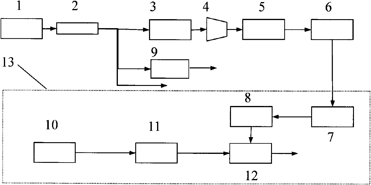
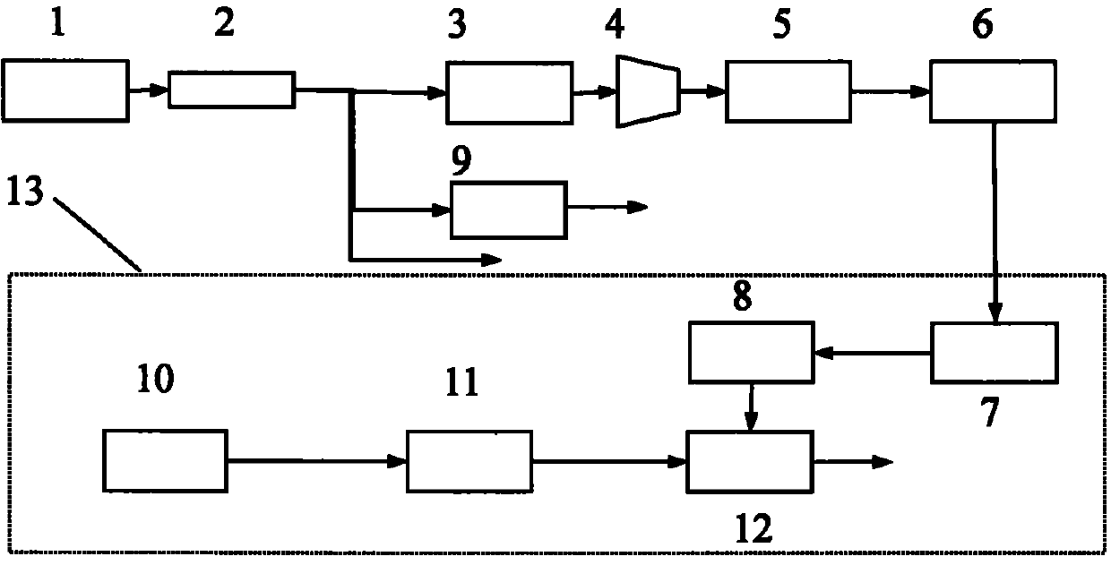
[0030] Please see first figure 1 , figure 1 It is a structural schematic diagram of an embodiment of the laser pulse synchronous triggering device of the present invention. As can be seen from the figure, the laser pulse synchronous trigger device of the present invention is composed of a short pulse laser system 1, a 1×N beam splitter 2, an optical pulse stacker 3, a high-speed photoelectric tube 4, a fast comparator 5, an electric amplifier 6, an electric pulse A generator 7, a pulse shaping plate 8, a first adjustable delayer 9, a long pulse laser 10, a second adjustable delayer 11 and an amplitude modulator 12 are formed, and the connection relationship is: the output of the short pulse laser system 1 The short-pulse laser is divided into N beams by the 1×N beam split...


PUM


Abstract

The invention discloses a laser pulse synchronous triggering device, which consists of a short pulse laser system, a 1*N splitter, an optical pulse accumulator, a high-speed photoelectric tube, a quick comparator, an electric pulse generator, a pulse shaping board, a first adjustable delayer, a long pulse laser, a second adjustable delayer and an amplitude modulator. The device is suitable to be used for high-stability signal triggering in a multipath laser pulse system and can realize the stable relative time control of multiple laser pulse signals. The device can improve the relative time stability of the output light of two laser systems to a picosecond order. The device has the characteristics of full fiber, compact structure, reliable operation and easy expansion.

Description


Claims


Application Information

Patent Timeline
Owner SHANGHAI INST OF OPTICS & FINE MECHANICS CHINESE ACAD OF SCI
Why Eureka
Try Eureka