Therapy apparatus

A treatment device and waveform technology, applied in the field of treatment devices, can solve the problems of complexity, increase in preparation time, increase in cost, etc., and achieve the effect of a simple circuit structure

Active Publication Date: 2010-12-08
OMRON HEALTHCARE CO LTD
View PDF2 Cites 7 Cited by
  • Summary
  • Abstract
  • Description
  • Claims
  • Application Information

AI Technical Summary

Problems solved by technology

In this adjustment work, manual work must be performed while checking the waveform with an oscilloscope, which is very troublesome, and leads to an increase in lead time and cost

Method used


Image

  • Therapy apparatus
  • Therapy apparatus
  • Therapy apparatus

Examples


Embodiment Construction

[0035] Hereinafter, best embodiments of the present invention will be described in detail with reference to the drawings. Here, a therapeutic device (low-frequency therapeutic device) using a low-frequency therapeutic current is exemplified.

[0036]

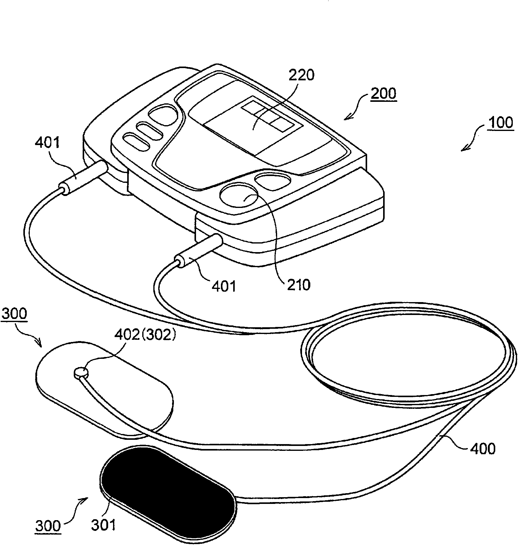
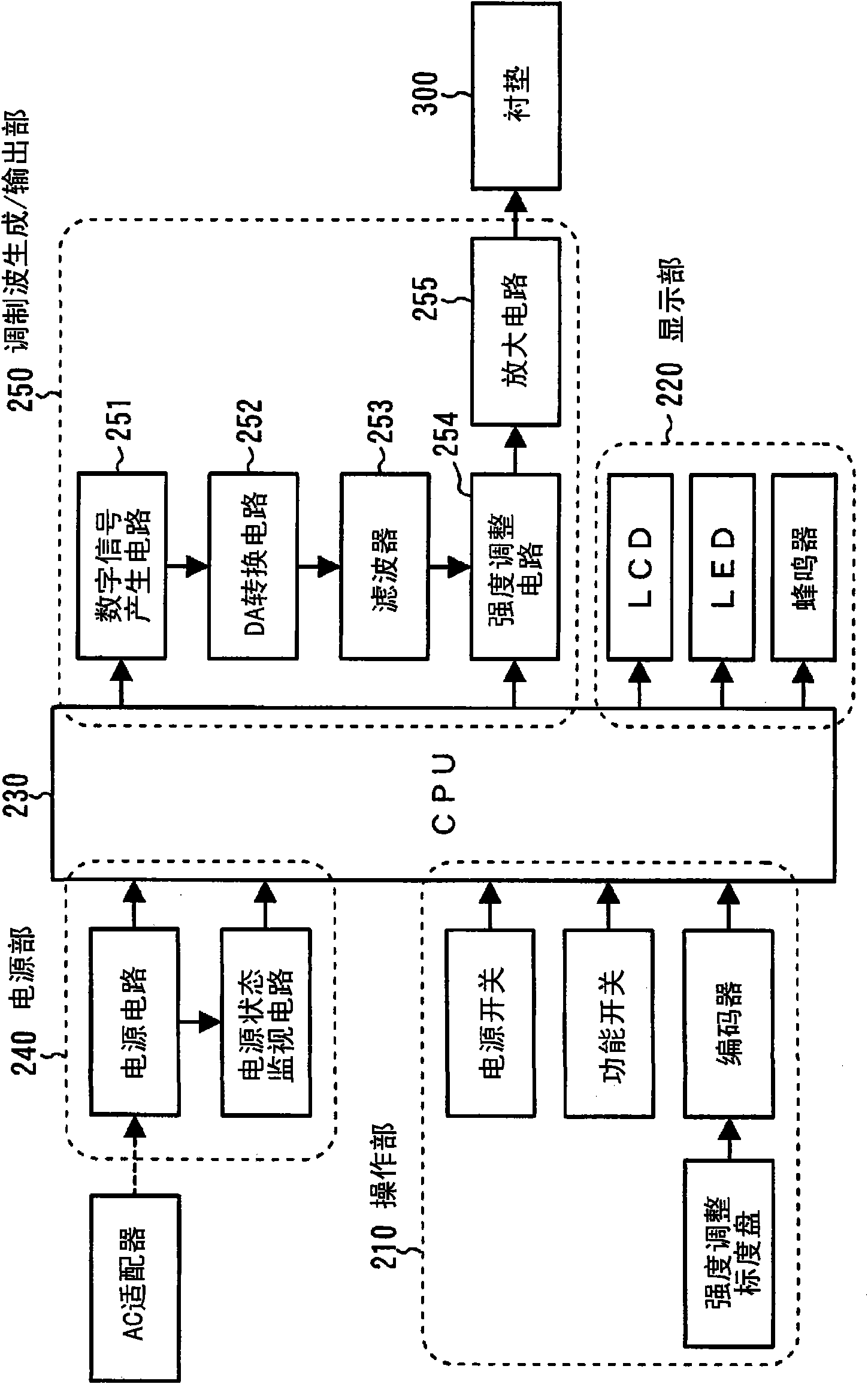
[0037] refer to figure 1 , figure 2 , the treatment device according to the embodiment of the present invention will be described. figure 1 It is a figure showing the appearance of the treatment device, figure 2 It is a block diagram schematically showing the hardware configuration of the therapeutic device.

[0038] The treatment device 100 is roughly composed of a treatment device main body 200, a pair of pads 300, and a flexible wire 400. The pair of pads 300 are used to stick the treatment device 100 on the treatment site, and the flexible wire 400 is used to make the treatment device body 200 and pad 300 are electrically connected.

[0039] The pad 300 is composed of a thin and highly flexible member. Electrodes...


PUM


Abstract

Waveform data to define a waveform of a modulation wave are stored at a memory of a digital signal generation circuit (251). The digital signal generation circuit (251) outputs a digital signal in accordance with selected waveform data. A DA conversion circuit (252) converts the digital signal to an analog signal to output an original waveform of the modulation wave. The original waveform is amplified by an amplification circuit (255), and a therapy waveform is output.

Description

technical field [0001] The present invention relates to a therapeutic device capable of outputting modulated waves as therapeutic current. Background technique [0002] There is known a therapeutic device in which a therapeutic current flows through the body through electrode pads, thereby exerting a massage-like effect. In this therapeutic device, a rectangular pulse wave is usually used as the therapeutic current, and the desired somatosensory sensation can be realized by controlling its wave height value / pulse width / rest width, etc. In addition, a therapeutic device of the type using an amplitude-modulated wave as a therapeutic current has also been proposed (see Patent Document 1). Pulse waves mainly stimulate muscles, while modulated waves stimulate tissues (nerves, joints, etc.) in muscles, and the therapeutic effects of the two differ in this regard. [0003] Such as Figure 9 As shown, in the existing therapeutic device, the modulated wave is generated by an analog...

Claims


Application Information

Patent Timeline
Patent Type & Authority Applications(China)
IPC IPC(8): A61N1/32
CPCA61N1/322A61N1/36014A61N1/0408A61N1/0472A61N1/36034
Inventor 藤田安生浅井里佳仓濑幸二村濑泰孝
Owner OMRON HEALTHCARE CO LTD
Why Eureka
Try Eureka