Fastening piece

A fastener and fastening technology, applied in rivets and other directions, can solve the problems of high time-consuming and cost, expensive and difficult to achieve quenching and tempering, and achieve reduction of molding load, elimination of complexity, and high strength capability. Effect

Active Publication Date: 2012-05-02
胡克国际公司
View PDF14 Cites 0 Cited by
  • Summary
  • Abstract
  • Description
  • Claims
  • Application Information

AI Technical Summary

Problems solved by technology

This further increases the cost and complexity of manufacturing the fastener
For example, two such heat treatment methods include: stress relief annealing and quenching and tempering; achieving consistent desired hardness by stress relief annealing is difficult to achieve and quenching and tempering is expensive without undesirable penetration of the collar surface. Difficult to achieve in the case of carbon or decarbonization
Both methods are time consuming and costly, e.g. additional charges for furnace operating costs are required

Method used


Image

  • Fastening piece
  • Fastening piece
  • Fastening piece

Examples


example 1

[0076] The purpose of the first experiment was to determine whether a collar manufactured to size HS5CF-R12 could be used as a headed collar to meet the Grade 8 value. The HS5CF-R12 fastener is a commercially available Grade 5 molded type fastener manufactured by Huck International, Inc. of Waco, Texas, USA.

[0077] The experiments involved testing the outside diameter (OD), hardness, swage load, tensile strength and preload of standard quenched and tempered Grade 8 collars and comparing them to Grade 5 collars such as cold heading collars. The results are expressed quantitatively in Table 1 below.

[0078] Table 1: Grade 5 Collars as Headed Collars

[0079]

[0080]

[0081] As shown in Table 1, the two collars "A" and "B" have 18% lower molded loads than the current standard HS8CF-R12 collar, and both meet the Grade 5 minimum industry tensile strength and preload requirements. Experiments have revealed that the collar, such as the cold heading collar, collar "A", ...

example 2

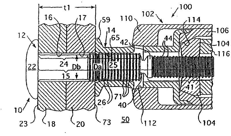
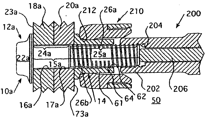
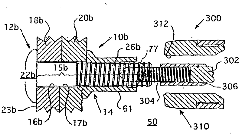
[0086] The second experiment arose out of a desire to develop an economical way to improve the life of safety tools and to reduce the cost of manufacturing Grade 8 collars. Specifically, the goal of the experiment was to determine whether a thinner walled, as-headed collar could increase snub load, reduce swage load and maintain the same tensile strength as a standard quenched and tempered collar and preload. The detent load is the load at which the collar 14 initially engages the pin lock slots 26, 26a, 26b, 26c, 26d. After this moment, plate (eg, workpieces 18, 20; 18a, 20a; 18b, 20b; 18c, 20c) clearance pullout is restricted because the collar 14 is seized on the pins 12, 12a, 12b, 12c, 12d. If the gap is maintained after the snub, the clamping force is reduced because instead of stretching the pins 12, 12a, 12b, 12c, 12d, the collar elongates to make the gap disappear.

[0087] HSCF-R20 made from the same processing sequence and raw material (50KSI tensile strength) were...

example 3

[0103] In addition to the results of the first two experiments, the third experiment also tested the effect of increasing the stiffness of the collar while reducing the wall thickness of the collar in an attempt to find the best balance of high strength and low mold load. Gap pullout results in less than optimal clamping force at the joint. However, as demonstrated in Example 2, increasing the collar stiffness also increased the mold force of the mounting collar. Reducing the collar wall thickness disproportionately lowers the mold force more than the stop (gap pull-out) load. Correspondingly, combining the findings of the preceding experiments, the installation is improved by balancing the increase in collar stiffness with a decrease in collar wall thickness to maintain the same tensile strength and preload, and increasing the stop load while reducing the molded load. Tool life, this experiment is expected to overcome known fastener design limitations. The purpose of this e...


PUM

PropertyMeasurementUnit
tensile strengthaaaaaaaaaa
hardnessaaaaaaaaaa

Abstract

The invention relates to a fastening piece, comprising a pin part; wherein the pin part is provided with an extension pin rod, and the extension pin rod can be arranged at an aiming opening in work piece. One side of work piece is jointed at the expanding head at one end of the pin. A slotted pin part extends and exceeds the corresponding side of the work piece. A shaft collar comprises a rob part, and the rod part is applicable to responding to mould pressing load applied between the pin part and the shaft collar such as cold heading shaft collar, so as to be pressed into the locking slot onthe pin part by moulding pressing. As a part of system, the shaft collar such cold heading shaft collar requires no heat treatment, and optimal balance of reducing shaft collar rod wall thickness andimproving hardness is provided, thus mould pressing load is minimum. The invention also provides low mould pressing load thread shape of the locking slot used for pin part and also discloses methods for reducing diameter, extending pin relative to shorter stretching part and improving mounting tool as well as related application method. The chuck is provided with a bump on the chuck, and the length of the stretching part is prolonged along the direction of the shaft collar by the bump, thus increasing the contact area with the anvil. The end part of the stretching part is not laminated to thediameter position in a line with the bottom of slot, thus improving shear strength of stretching addendum of the end part of the stretching part. The last stretching addendum of the stretching part is provided with a profile matched with the radius of an expanding stretcher of the last tooth of the chuck.

Description

technical field [0001] The present invention relates to fasteners, and more particularly, to fastening systems including multi-piece, molded type fasteners and their molding tools, the fastening system of which exhibits the optimum of low molding loads and high strength balance. The invention also relates to a simplified installation method using a low swage load fastening system. Background technique [0002] In many commercial applications, two-piece threaded or molded fasteners, commonly referred to as lock bolts, are commonly used to secure multiple workpieces together. See, eg, US Patent Nos. 2,531,048; No. 3,215,024; No. 3,915,053; No. 4,472,096; and No. 5,090,852. Depending on the commercial application in which the fasteners will be used, the material properties of these fasteners, such as tensile strength and hardness ((not limited to the Grade)) vary. To distinguish the various attributes of fasteners, fasteners are typically indicated by Grade. The Grade of a ...

Claims


Application Information

Patent Timeline
Patent Type & Authority Patents(China)
IPC IPC(8): B21J15/02F16B19/05
Inventor 拉里・D・默瑟罗伯特・J・克贝特
Owner 胡克国际公司
Why Eureka
Try Eureka