
Core tube structure system with transfer layer

A core tube and transfer layer technology, applied in special structures, building components, etc., can solve the problems of reducing the proportion of earthquake shear force, increasing the thickness of the core tube wall, increasing the cost, etc., reducing the axial force and increasing the vertical structure of the structure. The effect of the force transfer path

Pending Publication Date: 2019-06-07
TONGJI UNIV ARCHITECTURAL DESIGN INST GRP CO LTD
View PDF0 Cites 3 Cited by
  • Summary
  • Abstract
  • Description
  • Claims
  • Application Information

AI Technical Summary

Problems solved by technology

[0003] The traditional conventional structural system can no longer meet the requirements of architectural design. In order to adapt to the challenges brought about by different architectural concepts, structural engineers need to innovate the structural design of buildings, solve the structural force problems brought about by new architectural shapes, and strengthen the structure. The integration of form and architectural concept satisfies the safety, applicability and durability of the building as a whole, and realizes the beauty of the structure to achieve the building
[0004] For high-quality offices, the bottom floor is expected to be transparent, and the outer frame should minimize structural components, which will inevitably lead to the inability of a large number of vertical components of the outer frame to land, the vertical load transmission is discontinuous, and the force transmission is not direct. At the same time, for the steel frame-core tube structure, The reduction in the number of vertical components of the outer frame at the bottom floor will reduce the proportion of the seismic shear force borne by the outer frame. Most of the seismic shear force of the floors is borne by the reinforced concrete core tube, which will greatly increase the wall thickness of the core tube and occupy the building space. At the same time, the amount of steel bars and steel frames in the wall increases, which increases the cost

Method used

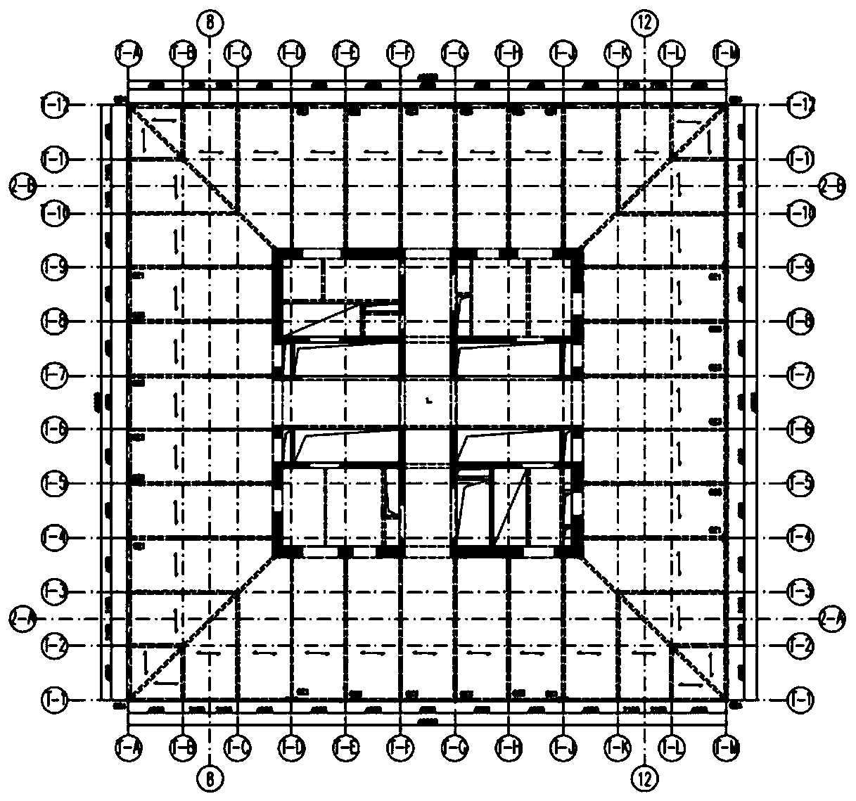
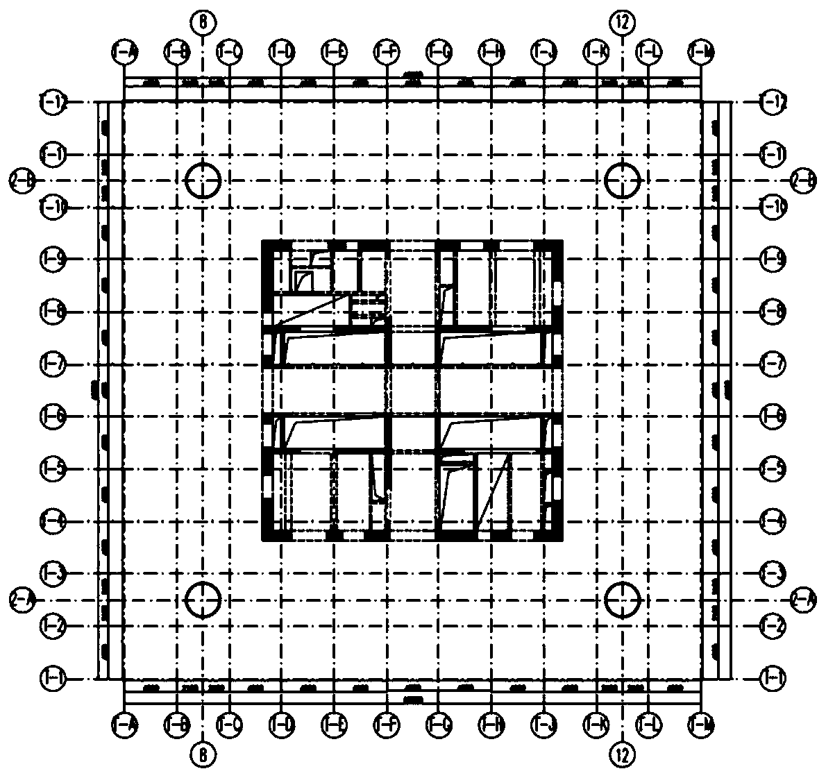
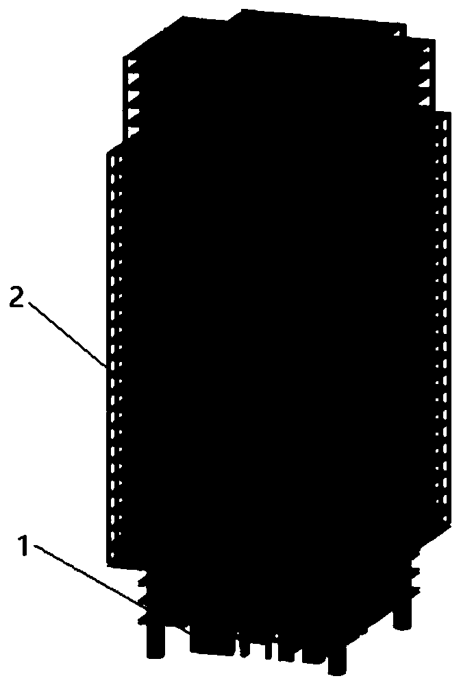

Image

  • Core tube structure system with transfer layer
  • Core tube structure system with transfer layer
  • Core tube structure system with transfer layer

Examples


Embodiment Construction

[0026] The present invention will be described in detail below in conjunction with the accompanying drawings and specific embodiments. This embodiment is carried out on the premise of the technical solution of the present invention, and detailed implementation and specific operation process are given, but the protection scope of the present invention is not limited to the following embodiments.

[0027] This embodiment provides a core tube structure system with a conversion layer, including a core tube 1 and an outer frame 2, and the outer frame 2 is arranged on the periphery of the core tube 1, such as image 3 shown.

[0028] The outer frame 2 is an outer frame with a conversion structure, including a frame body and an umbrella-shaped conversion layer. The system adopts an umbrella-shaped transfer layer, so that the upper outer frame column does not fall to the ground, which meets the requirements of the architectural form, and at the same time increases the vertical force ...


PUM


Abstract

The invention relates to a core tube structure system with a transfer layer. The core tube structure system with the transfer layer comprises a core tube and an outer frame, the outer frame is arranged on the periphery of the core tube, the outer frame is an outer frame with a transfer structure, and a connected frame body and an umbrella shape transfer layer are included. The core tube structuresystem is a high-rise structure system with a shelter layer. In the shelter layer, a prestressed cable-stayed cable is connected between the outer frame and the core tube. Compared with the prior art,the core tube structure system with the transfer layer meets the requirements of a building form and meanwhile, increases the vertical force transmission path of the structure; the vertical load of the outer frame is transferred to the core tube in batches through the cable, the load of an outer frame column and a lower part transfer structure is reduced, and the structural redundancy is increased; and meanwhile, a viscous damping wall is arranged in the core tube, the seismic force of the core tube of reinforced concrete of a lower part floor is reduced, and the thickness of the core tube wall and the amount of steel bars and steel bones are reduced.

Description

technical field [0001] The invention relates to the technical field of building structure design, and relates to a core tube shock absorbing structure, in particular to a core tube structure system with a transfer layer. Background technique [0002] Due to the continuous development of economies around the world, the application of high-rise building structures is becoming more and more extensive. Its architectural functions are mainly concentrated in commercial offices and hotel apartments. High-quality offices often hope that the bottom floors are transparent and the structural components are minimized. This gives The design of the building structure brings great difficulties and challenges. [0003] The traditional conventional structural system can no longer meet the requirements of architectural design. In order to adapt to the challenges brought about by different architectural concepts, structural engineers need to innovate the structural design of buildings, solve t...

Claims


Application Information

Patent Timeline
IPC IPC(8): E04B1/34
Inventor 郑超毅吴宏磊
Owner TONGJI UNIV ARCHITECTURAL DESIGN INST GRP CO LTD
Learn More