Multi-tube-bank superheater of waste heat boiler

A waste heat boiler and superheater technology, used in steam superheating, lighting and heating equipment, steam generation and other directions, can solve the problems of high design difficulty of heating surface, poor operation safety, etc. The effect of improving safety and simple structure

Pending Publication Date: 2020-12-18
MHPS DONGFANG BOILER CO LTD
View PDF0 Cites 2 Cited by
  • Summary
  • Abstract
  • Description
  • Claims
  • Application Information

AI Technical Summary

Problems solved by technology

[0006] The present invention mainly solves the technical defects in the prior art that the operation safety is poor and the design of the heating surface is difficult due to the large temperature difference between the front and rear rows of heating surfaces, and provides a temperature difference between the front and rear rows of heating surfaces. Multi-tube row superheater with smaller size, better operating safety, and looser design conditions on the heating surface

Method used


Image

  • Multi-tube-bank superheater of waste heat boiler
  • Multi-tube-bank superheater of waste heat boiler
  • Multi-tube-bank superheater of waste heat boiler

Examples


Embodiment 1

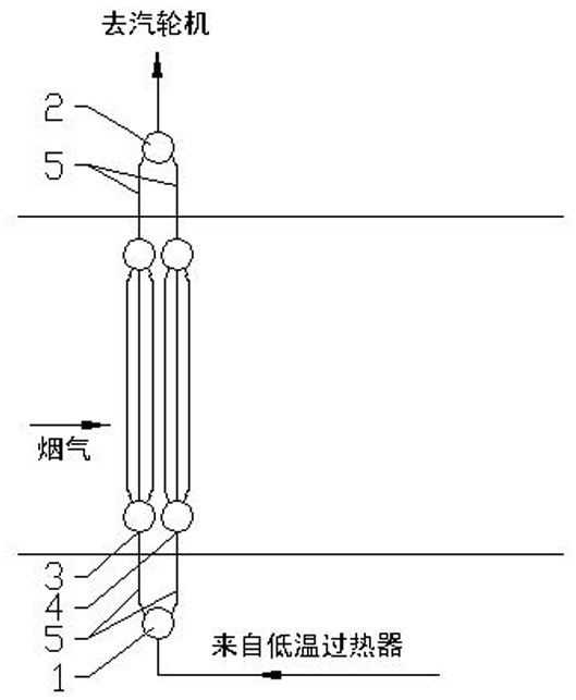
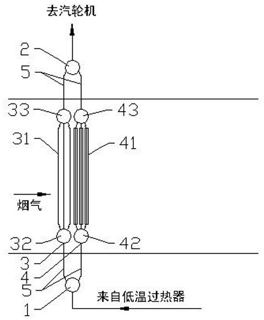
[0022]Example 1: As attachedfigure 2 , AttachedFigure 4 As shown, the present invention includes a steam inlet header 1, a tube group outlet header 2, and a first tube panel 3 and a second tube panel 4 arranged in parallel between the steam inlet header 1 and the tube group outlet header 2. A tube panel 3 is located on the front side of the second tube panel 4 with respect to the flue gas flow;

[0023]The first tube panel 3 includes a first tube panel inlet header 32 connected to the steam inlet header 1 through a connecting tube 5, and a first tube panel outlet header 33 connected to the tube group outlet header 2 through the connecting tube 5, arranged in Three rows of first heating surfaces 31 between the first tube panel inlet header 32 and the first tube panel outlet header 33, the first heating surface 31 uses light tubes;

[0024]The second tube panel 4 includes a second tube panel inlet header 42 connected to the steam inlet header 1 through a connecting tube 5, and a second tub...

Embodiment 2

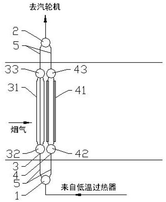
[0030]Example 2: As attachedimage 3 , AttachedFigure 4 As shown, the present invention includes a steam inlet header 1, a tube group outlet header 2, and a first tube panel 3 and a second tube panel 4 arranged in parallel between the steam inlet header 1 and the tube group outlet header 2. A tube panel 3 is located on the front side of the second tube panel 4 with respect to the flue gas flow;

[0031]The first tube panel 3 includes a first tube panel inlet header 32 connected to the steam inlet header 1 through a connecting tube 5, and a first tube panel outlet header 33 connected to the tube group outlet header 2 through a connecting tube 5, arranged Three rows of first heating surfaces 31 between the first tube panel inlet header 32 and the first tube panel outlet header 33, and the first heating surface 31 adopts light tubes;

[0032]The second tube panel 4 includes a second tube panel inlet header 42 connected to the steam inlet header 1 through a connecting tube 5, and a second tub...


PUM


Abstract

The invention relates to a multi-tube-bank superheater of a waste heat boiler and belongs to the technical field of power station boiler equipment. The multi-tube-bank superheater comprises a steam inlet header, a tube bank outlet header, a first tube panel and a second tube panel; the first tube panel and the second tube panel are arranged in parallel and connected with the steam inlet header andthe tube bank outlet header through connecting tubes correspondingly; a plurality of rows of first heating surfaces are arranged on the first tube panel; a plurality of rows of second heating surfaces are arranged on the second tube panel; the first heating surfaces adopt light tubes; the second heating surfaces adopt finned tubes; and the first tube panel is located on the front side of the second tube panel relative to the smoke flow direction. According to the multi-tube-bank superheater of the waste heat boiler, the technical problem that in the prior art, large temperature difference exists between the wall temperatures of the front rows of heating surfaces and the wall temperatures of the rear rows of heating surfaces is solved, the design difficulty of the heating surfaces is lowered, the risk that leakage and pipe explosion are prone to happening to welded junctions where the heating surfaces are connected with the headers is avoided, and unit operation safety is improved.

Description

Technical field[0001]The invention relates to a superheater of a waste heat boiler, in particular to a multi-tube row superheater of a waste heat boiler, belonging to the technical field of power station boiler equipment.Background technique[0002]With the large-scale gas turbine waste heat boiler, the temperature, pressure, and flow parameters of the high-pressure main steam and reheat steam are very high. In order to avoid vibration caused by the excessively high steam flow rate in the tube of the superheater, and at the same time to avoid the resistance of the heating surface affecting the evaporation of the waste heat boiler, the existing solution is: the superheater adopts two sets of tube panels arranged in parallel, and each tube panel is arranged in several rows The heating surface and the heating surface tube are uniformly used for light tubes or uniformly used finned tubes to form a multi-tube row superheater. By arranging multiple rows of heating surfaces, it is possible t...

Claims


Application Information

Patent Timeline
Patent Type & Authority Applications(China)
IPC IPC(8): F22G3/00F22G7/12
CPCF22G3/002F22G3/007F22G7/12
Inventor 林正春李文杰邓倩刘彬武张澈周立刚叶洲海王翔
Owner MHPS DONGFANG BOILER CO LTD
Why Eureka
Try Eureka