Movable manned elevator and elevator working mechanism thereof

A technology of working mechanism and elevator, applied in the direction of lifting device, etc., can solve the problems of unreasonable boom structure, poor synchronization, poor stability, etc., and achieve the effect of improving load capacity, reducing load, and increasing torque

Inactive Publication Date: 2010-12-15
SANY GRP +1
View PDF10 Cites 8 Cited by
  • Summary
  • Abstract
  • Description
  • Claims
  • Application Information

AI Technical Summary

Problems solved by technology

[0004] The purpose of the present invention is to provide a manned lift, which solves the problems of unreasonable structure, poor synchronization and poor stability of the arm frame of the existing manned lift

Method used


Image

  • Movable manned elevator and elevator working mechanism thereof
  • Movable manned elevator and elevator working mechanism thereof
  • Movable manned elevator and elevator working mechanism thereof

Examples


Embodiment Construction

[0034] The embodiments of the present invention will be described in detail below with reference to the accompanying drawings, but the present invention can be implemented in many different ways defined and covered by the claims.

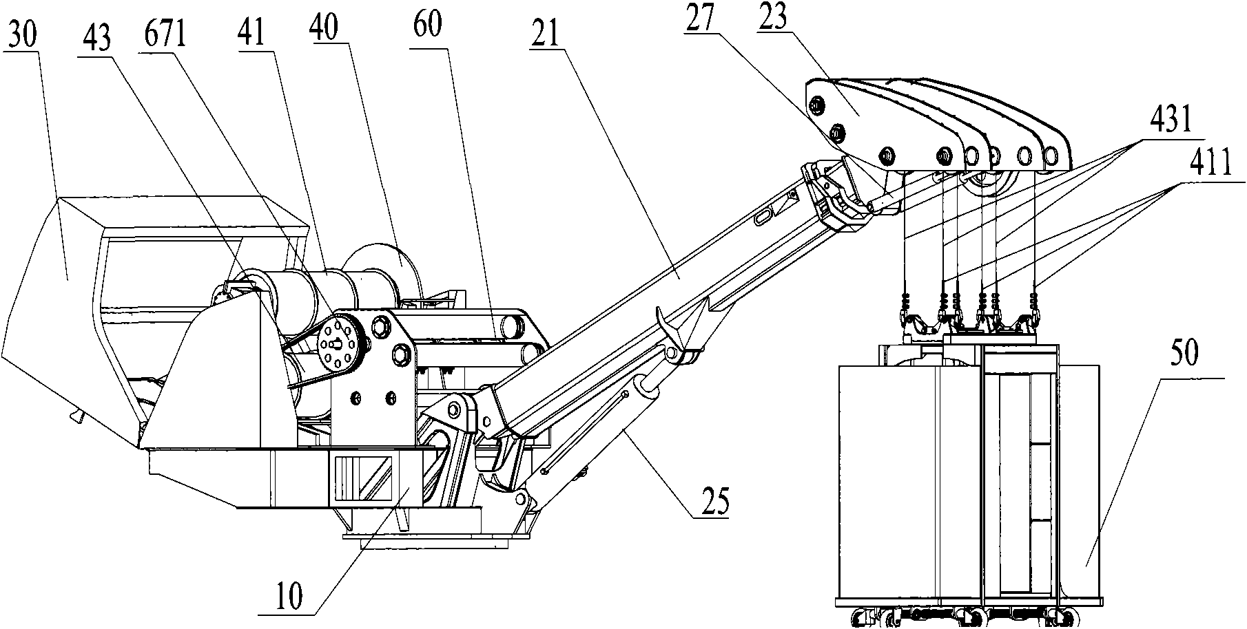
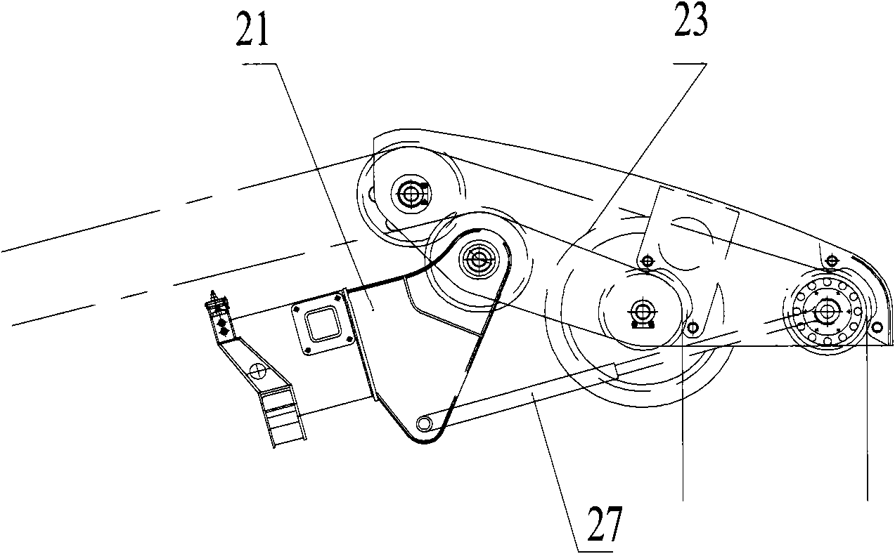
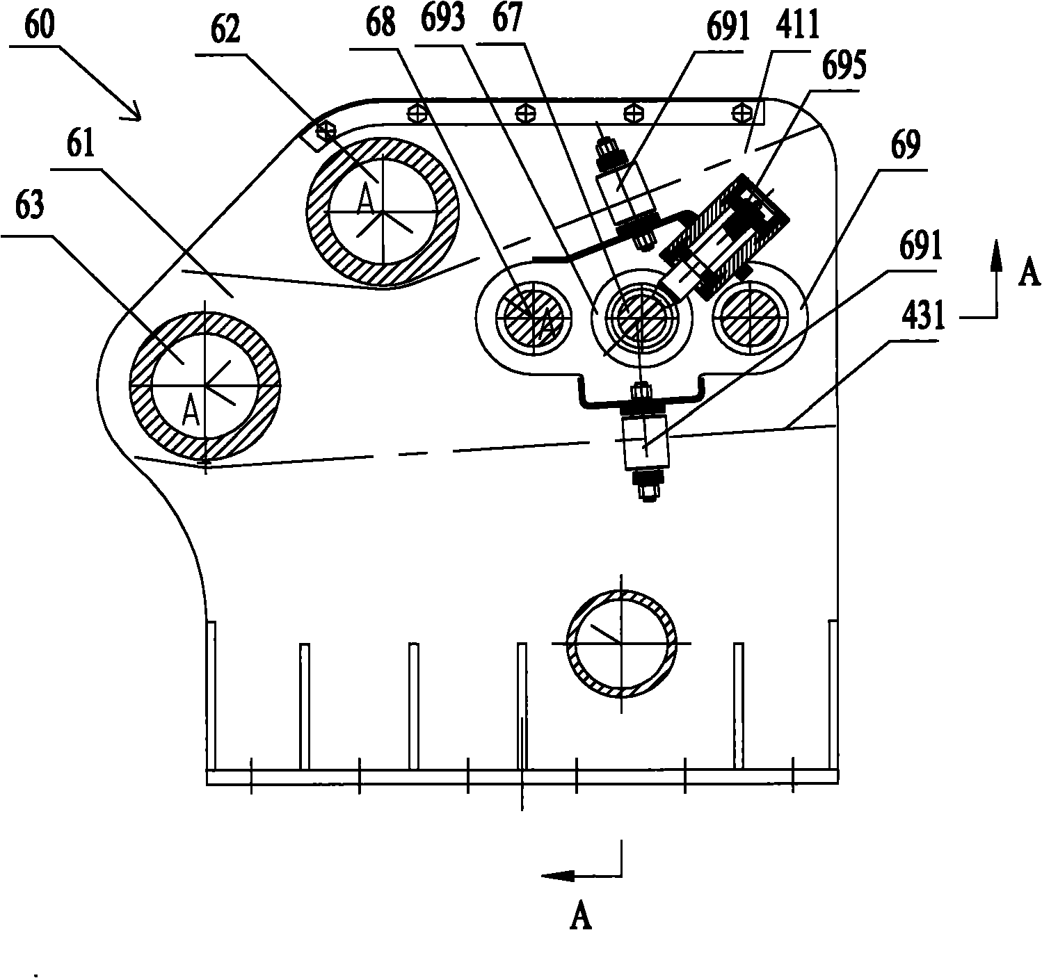
[0035] figure 1 A schematic structural diagram of a lifting working mechanism of a people lift used for a people lift according to an embodiment of the present invention is shown. Such as figure 1 As shown, the lifting working mechanism for a manned lift includes: a turntable receiving seat 10; The boom mechanism is hinged with the turntable receiving seat 10 . The counterweight 30 is connected to the side of the turntable receiving seat 10 away from the boom mechanism. The winch assembly 40 is arranged on the turntable receiving seat 10, between the boom mechanism 20 and the counterweight 30, and controls the retraction and release of the suspension steel rope. The cage 50 is connected with the arm head piece 23 by a suspension steel rope. Suc...


PUM


Abstract

The invention discloses an elevator working mechanism for a manned elevator, which comprises a turntable bearing seat, a cantilever crane mechanism, a counter weight, a winch assembly and a cage. The cantilever crane mechanism comprises a suspension arm assembly, an amplitude cylinder, an arm head part and a leveling cylinder, wherein one end of the suspension arm assembly is hinged on the turntable bearing seat; two ends of the amplitude cylinder are connected with the turntable bearing seat and the suspension arm assembly respectively, and the amplitude cylinder is used for driving the suspension arm assembly to rotate longitudinally around the turntable bearing seat; the arm head part is pivotably connected with the second end of the suspension arm assembly; and two ends of the leveling cylinder is movably connected with the turntable bearing seat and the arm head part respectively to form a triangle structure, and the leveling cylinder is used for matching with the amplitude cylinder to control a pivot angle of the arm head part relative to the suspension arm assembly. Due to the adoption of the stable triangle structure formed among the leveling cylinder, the suspension arm assembly and the arm head part, the elevator working mechanism for the manned elevator solves the problems of low synchronicity of the suspension arms which are controlled by two elevators and low stability and safety of the cage in the prior art; meanwhile, the invention also provides a movable manned elevator.

Description

technical field [0001] The invention relates to a lifting working mechanism for a people lift and a mobile people lift comprising it. Background technique [0002] The mobile manned lift is mainly used in the maintenance of equipment below the water level, the rescue of personnel, the transportation of materials and other occasions. With the increase of the scope of use of the mobile man lift, it has received more and more attention. [0003] Most of the existing mobile manned lifts adopt a parallelogram boom structure, which is mainly composed of two booms controlled by two hoists respectively, wherein a single boom consists of a main boom, a horizontal boom head, a tie rod , composed of two steel rope guide pulleys and a base. The two ends of the main boom and the pull rod are respectively hinged between the horizontal boom head and the base to form a parallelogram structure. Two steel rope guide pulleys are respectively installed on the horizontal boom head. The upper a...

Claims


Application Information

Patent Timeline
IPC IPC(8): B66F11/04
Inventor 彭国成廖向宇梅景平
Owner SANY GRP
Why Eureka
Try Eureka