Loom transmission mechanism

A technology of transmission mechanism and driving mechanism, which is applied in looms, textiles, textiles and papermaking, etc., can solve the problem of tooth slippage, unable to find weft breakage, etc., and achieve the effects of convenient operation, simple and reasonable structure, and accurate control.

Active Publication Date: 2012-03-28
广东康特斯织造装备有限公司
View PDF2 Cites 0 Cited by
  • Summary
  • Abstract
  • Description
  • Claims
  • Application Information

AI Technical Summary

Problems solved by technology

The function of the gear tooth element of this structure is to stop the element group to be driven. After long-term use, the phenomenon of slipping teeth is prone to occur, causing the component group to be driven to stop and cannot be stopped, so that the work of finding broken wefts cannot be realized

Method used


Image

  • Loom transmission mechanism
  • Loom transmission mechanism
  • Loom transmission mechanism

Examples


no. 1 example

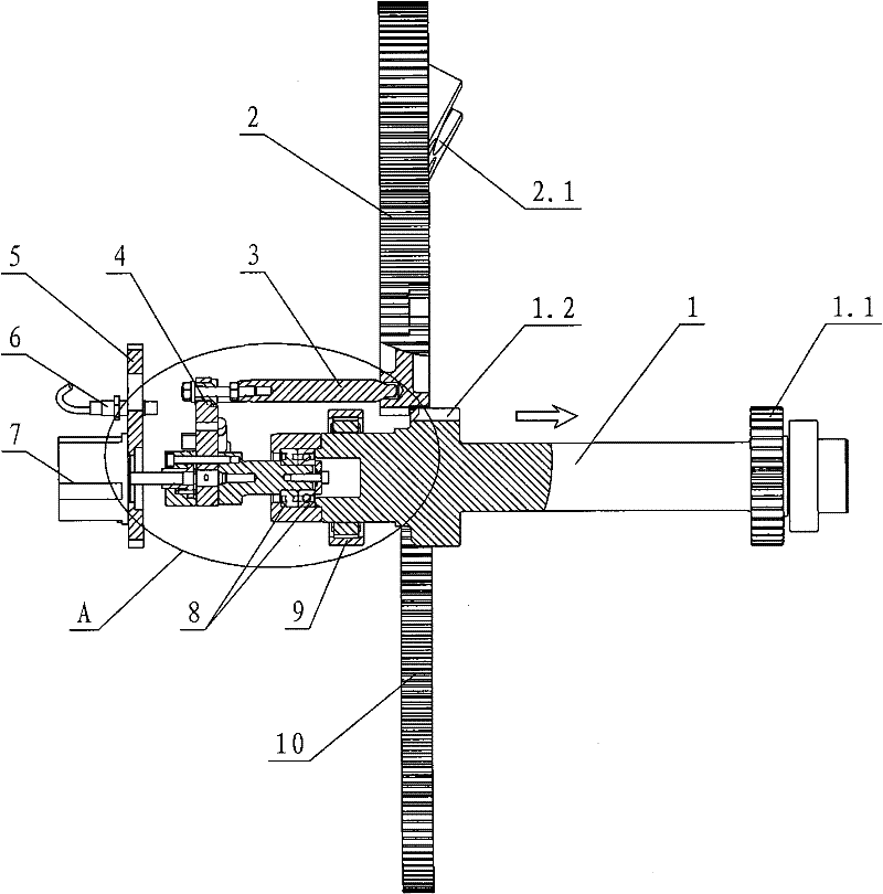
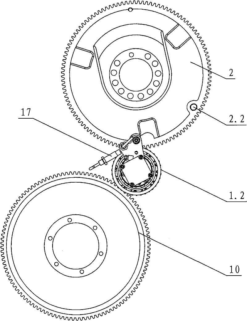
[0026] see Figure 1-Figure 4 , the transmission mechanism of the loom includes a main shaft driven by a drive motor, a transmission shaft of a beating mechanism connected to the main shaft, an input shaft of an opening mechanism, a driving mechanism for controlling the axial movement of the main shaft, and a stopper for stopping the transmission shaft of the beating mechanism. The driving device, the main shaft is axially slidably arranged in the casing, and the output shaft of the drive motor, the beating-up mechanism transmission shaft and the shedding mechanism input shaft are respectively provided with a driving gear, a beating-up driving gear 2 and a shedding driving gear 10. The main shaft is a double gear shaft 1 with a first gear 1.1 and a second gear 1.2 respectively arranged at the front and rear ends; the first gear meshes with the drive gear, and the second gear meshes with the beating-up drive gear and the opening drive gear.

[0027] The driving mechanism is a m...

no. 2 example

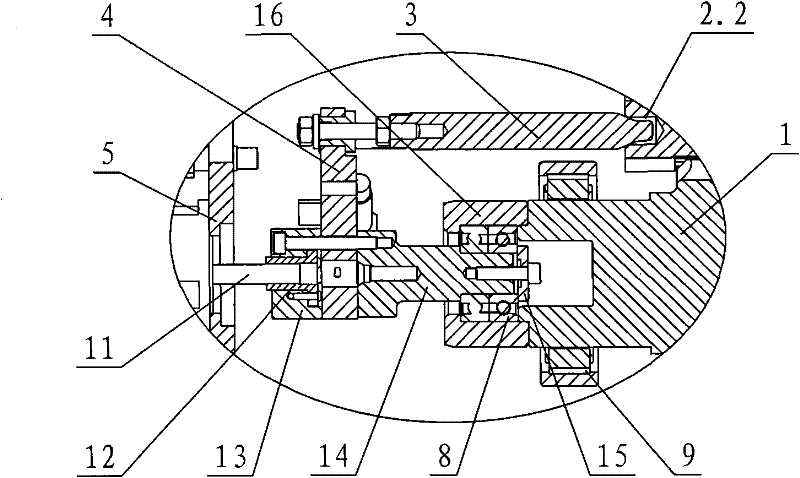
[0032] see Figure 5-Figure 8 , the transmission mechanism of the loom comprises a main shaft driven by a drive motor 26, a beating mechanism transmission shaft 25 and an opening mechanism input shaft 23 respectively connected to the main shaft transmission, a driving mechanism for controlling the axial movement of the main shaft, and a beating mechanism transmission shaft The stopping device for stopping, the main shaft is axially slidably arranged in the box, and the output shaft of the drive motor, the transmission shaft of the beating mechanism and the input shaft of the shedding mechanism are respectively provided with a driving gear 22, a beating driving gear 2 and a shedding driving gear 10. The main shaft is a double gear shaft 1 with a first gear 1.1 and a second gear 1.2 respectively arranged at the front and rear ends; the first gear meshes with the drive gear, and the second gear meshes with the beating-up drive gear and the opening drive gear.

[0033] The drivin...


PUM


Abstract

The invention discloses a loom transmission mechanism, which comprises a main shaft driven by a driving motor, a beating-up mechanism transmission shaft and a shedding mechanism input shaft in transmission connection with the main shaft respectively, a driving mechanism for controlling axial movement of the main shaft and a stop device for stopping the beating-up mechanism transmission shaft, wherein the main shaft is axially and glidingly arranged in a box body; the output shaft of the driving motor, the beating-up mechanism transmission shaft and the shedding mechanism input shaft are provided with a driving gear, a beating-up driving gear and a shedding driving gear respectively; the main shaft is a double-gear shaft, the front end and the rear end of which are provided with a first gear and a second gear respectively; and the first gear is engaged with the driving gear, and the second gear is engaged with the beating-up driving gear and the shedding driving gear. Under the condition that the conventional driving motor is not changed, when double-gear shaft transmission is adopted and the front and rear axial movement of the double-gear shaft is ensured, the first and second gear are engaged with the driving gear and the shedding driving gear all the time, and when the second gear moves, the second gear is engaged with or separated from the beating-up driving gear.

Description

technical field [0001] The invention relates to a textile machine, in particular to a loom transmission mechanism. Background technique [0002] Chinese Patent Document No. CN1243555 disclosed a driving device for a loom on February 2, 2000. Its main drive shaft is supported in a box and driven by a drive motor. The motor and the main drive shaft are arranged coaxially. And directly connected with this axis. The main shaft is the motor shaft of the drive motor. Because the axial movable range of the motor shaft of the existing motor is very small, and the main shaft of this structure needs to be separated from a driving gear through a relatively large axial movement under certain circumstances, but because the main shaft is the relationship between the motor shaft, so The entire motor must be refitted to achieve a large range of axial movement of the motor shaft. [0003] Chinese Patent Document No. CN1997785 on July 11, 2007, discloses a driving device for a loom, which ...

Claims


Application Information

Patent Timeline
Patent Type & Authority Patents(China)
IPC IPC(8): D03D49/30D03D49/24
Inventor 戴晓晗夏云科吴和福
Owner 广东康特斯织造装备有限公司
Why Eureka
Try Eureka