Variable geometric turbine nozzle ring

A technology of nozzle ring and geometry, which is applied in the direction of engine components, machines/engines, internal combustion piston engines, etc., can solve the problem of high cost

Active Publication Date: 2010-12-15
CUMMINS TURBO TECH
View PDF14 Cites 16 Cited by
  • Summary
  • Abstract
  • Description
  • Claims
  • Application Information

AI Technical Summary

Problems solved by technology

As a result, the costs associated with producing the nozzle ring and associated linkages are quite high and it is therefore desirable to reduce these costs as much as possible

Method used


Image

  • Variable geometric turbine nozzle ring
  • Variable geometric turbine nozzle ring
  • Variable geometric turbine nozzle ring

Examples


Embodiment Construction

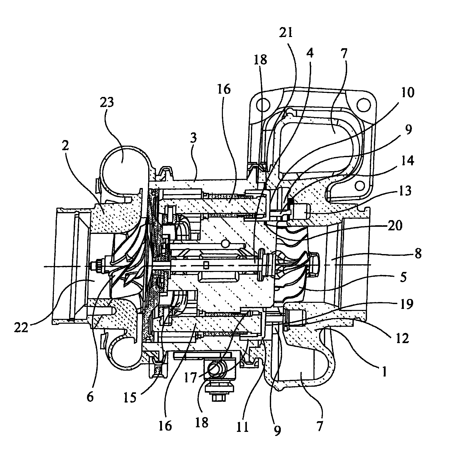
[0075] refer to figure 1 , which shows a known variable geometry turbocharger comprising a housing consisting of a variable geometry turbine housing 1 and a compressor housing 2 interconnected by a central bearing housing 3 . The turbocharger shaft 4 extends from the turbine housing 1 via the bearing housing 3 to the compressor housing 2 . A turbine wheel 5 is mounted on one end of the shaft 4 to rotate within the turbine housing 1 , and a compressor wheel 6 is mounted on the other end of the shaft 4 to rotate within the compressor housing 2 . The shaft 4 rotates about a turbocharger axis 4 a on a bearing assembly inside the bearing housing 3 .

[0076] The turbine housing 1 defines an inlet volute 7 to which gases from an internal combustion engine (not shown) are conveyed. Exhaust gas flows from the inlet volute 7 to the axial outlet channel 8 via the annular inlet channel 9 and the turbine wheel 5 . The inlet channel 9 is delimited on one side by a face 10 of a radial wa...


PUM


Abstract

The invention discloses a nozzle ring used in variable geometric turbine and the variable geometric turbine having the nozzle ring, such as a variable geometric turbocharger; also discloses a method for producing the nozzle ring. The nozzle ring comprises a radial wall which limits a first radial surface; a blade group is extended from the first radial surface; and the first radial surface is extended backwards to form a flange which is located inside or outside while extended along the axial direction; the nozzle ring is an assembly composed of a first part and a second part; the first part comprises a support member for supporting at least one of the blades; the second part is used for limiting the flange located inside or outside while extended along the axial direction, and limiting one or more axially extended apertures which construct the axial flow path of the second part for gases to flow through in use.

Description

technical field [0001] The invention relates to a nozzle ring for use in a variable geometry turbine and a variable geometry turbine incorporating said nozzle ring, such as a variable geometry turbocharger. More specifically, but not exclusively, nozzle rings may be used in variable geometry turbines of diesel powered internal combustion engines. Background technique [0002] A turbocharger is a well known device for supplying air to the intake of an internal combustion engine at a pressure above atmospheric pressure (boost pressure). A conventional turbocharger essentially consists of a housing in which an exhaust gas driven turbine wheel is provided mounted on a rotatable shaft connected downstream of the engine outlet manifold. Rotation of the turbine wheel rotates a compressor wheel mounted on the other end of the shaft. The compressor wheel delivers compressed air to the engine inlet manifold. Traditionally, turbocharger shafts are supported by journals and thrust be...

Claims


Application Information

Patent Timeline
Patent Type & Authority Applications(China)
IPC IPC(8): F01D17/16F02B37/24
CPCY02T10/144Y02T10/12
Inventor 汤姆·詹姆士·罗伯茨罗伯·霍尔罗伊德约翰·帕克
Owner CUMMINS TURBO TECH
Why Eureka
Try Eureka