Three-dimensional shape measuring method and device

A technology of three-dimensional shape and measurement method, which is applied in the direction of measuring device, optical device, geometric characteristics/aberration measurement, etc., and can solve the problems that the measurement takes a lot of time and is complicated

Inactive Publication Date: 2010-12-15
FUJI PHOTO OPTICAL CO LTD
View PDF9 Cites 31 Cited by
  • Summary
  • Abstract
  • Description
  • Claims
  • Application Information

AI Technical Summary

Problems solved by technology

[0018] Therefore, a method different from the measurement of the shape of the lens surface has been proposed for the measurement of surface deviation or surface inclination. Methods of calculating surface deviation and surface inclination, etc., but other measurements than lens surface shape measurement are complicated and require a lot of time for measurement

Method used


Image

  • Three-dimensional shape measuring method and device
  • Three-dimensional shape measuring method and device
  • Three-dimensional shape measuring method and device

Examples


no. 1 Embodiment approach

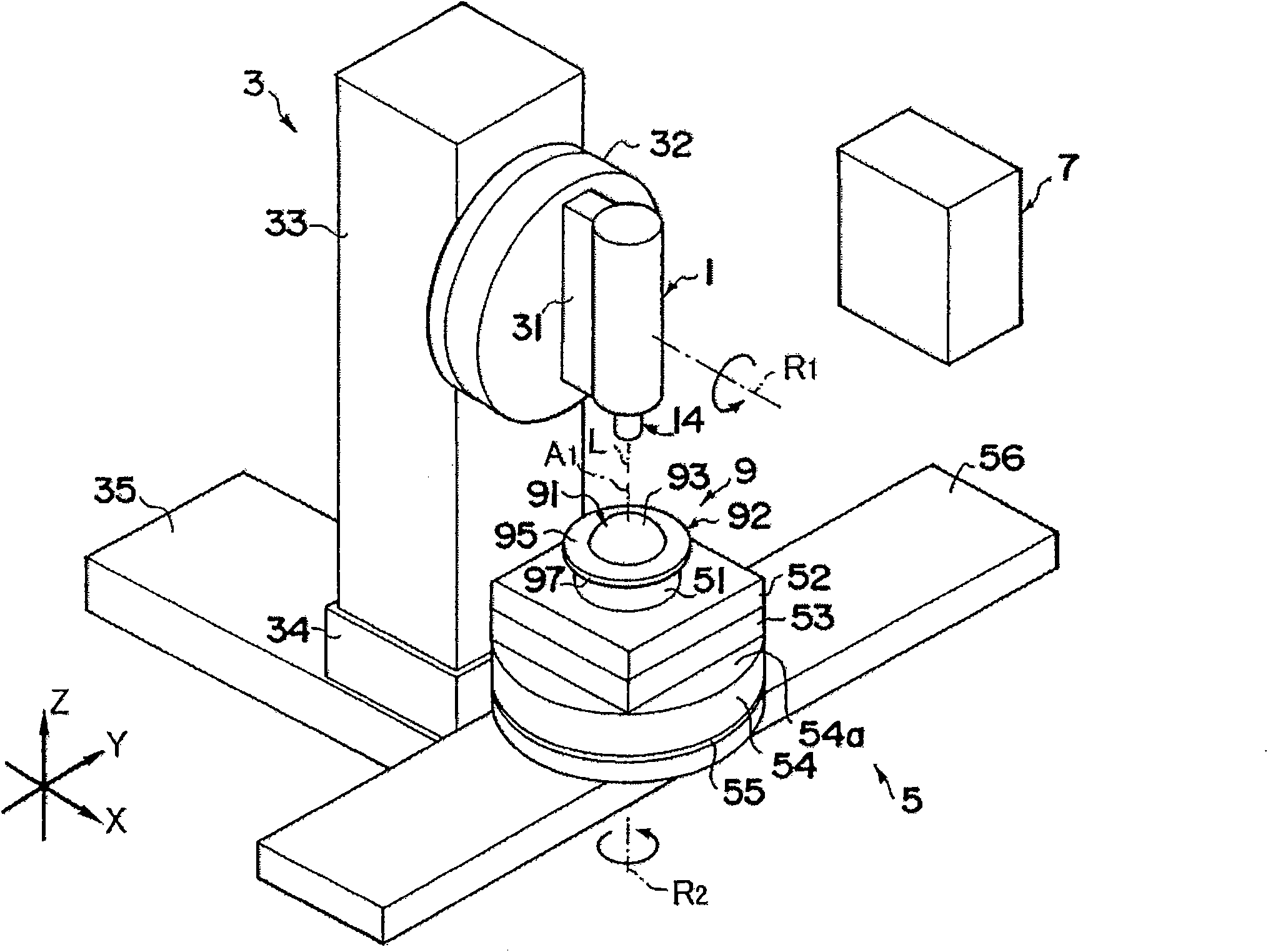
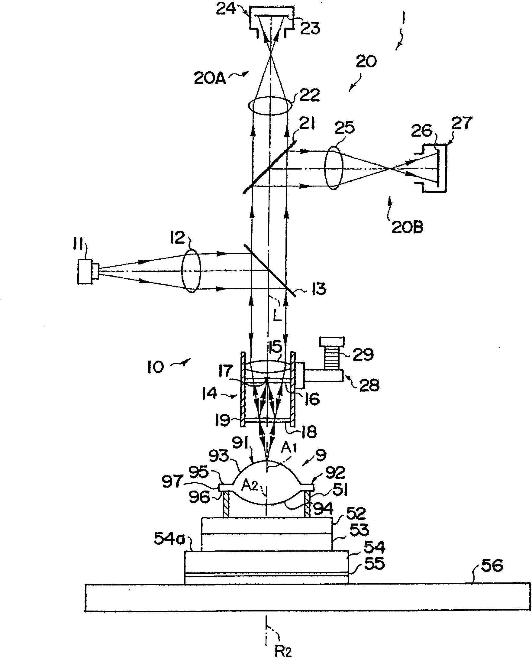
[0125] First, based on Figure 6 to Figure 8 , the configuration of the lens 9 to be measured as the object to be measured in the first embodiment and the items to be measured will be described.

[0126] Such as Image 6 The illustrated lens 9 under test includes a lens portion 91 and a flange-shaped edge portion 92 formed on the outer peripheral portion of the lens portion 91 . The lens portion 91 is designed to be formed with the first axis A 1 The first curved surface 93 (consisting of an aspheric surface) and the second axis A 2 The second curved surface 94 (consisting of a spherical surface) in the shape of a rotating surface is formed at the center, and the edge portion 93 has an edge portion surface 95 and an edge portion back surface 96 respectively formed in an annular shape, and an edge portion side surface formed in a cylindrical shape. 97 and constituted. In addition, the first axis A 1 In design, it becomes the central axis of the outer diameter of the first ...

no. 2 Embodiment approach

[0210] Next, based on Figure 19 , Figure 20 The configuration of the measured lens 109 as the measured object of the second embodiment and the items to be measured will be described.

[0211] Such as Figure 19 As shown, the lens under test 109 is designed to have: formed with the first axis A 11 The surface of the test object formed by the first curved surface 191 (consisting of an aspherical surface) in the shape of a rotating surface at the center is formed by forming a surface along the second axis A 12 The rear surface of the test object is formed of a second curved surface 192 (consisting of a spherical surface) in the form of a rotating surface at the center, and a cylindrical edge surface 193 (end surface of the lens under test 109 ) is formed.

[0212] In addition, in the second embodiment, the surface of the sample and the back surface of the sample are defined as described above, but the Figure 19 The surface on the upper side of the test lens 109...


PUM


Abstract

A process of measuring a shape while changing the relative posture of an microscopic interferometer (1) to a sample lens (9) which is rotated about a rotation axis (R2) is divided into a process of measuring a top surface in a state where the sample lens (9) is supported from a back surface and a process of measuring a back surface in a state where the sample lens is supported from the top surface. By combining first shape information of a flange side surface (97) acquired by the process of measuring the top surface and second shape information of the flange side surface (97) acquired by the process of measuring the back surface, the relative positional relation between the sample top surface and the sample back surface is calculated.

Description

technical field [0001] The present invention relates to a three-dimensional shape measuring method and device for measuring the shape of an object to be measured, such as an aspheric lens, and in particular to a method and device suitable for obtaining the positional deviation of the central axes between the front and back surfaces or the measured object in addition to the shapes of the surface and back of the object to be measured. A three-dimensional shape measurement method and device for various shape information related to a measured body, such as the roundness of the side surface of the body. Background technique [0002] Conventionally, it is known that a spherical wave is irradiated on the surface or back of an object to be measured (hereinafter sometimes referred to as "measured surface") such as an aspherical lens, and based on the interference formed by the return light from the measured surface and the interference of reference light, It is a method of specifying...

Claims


Application Information

Patent Timeline
Patent Type & Authority Applications(China)
IPC IPC(8): G01B11/24
CPCG01M11/025G01M11/0221G01M11/0271G01B11/2441
Inventor 葛宗涛富水政昭神田秀雄斋藤隆行小泉升持立诚仁鹰野滋之岩崎裕行
Owner FUJI PHOTO OPTICAL CO LTD
Why Eureka
Try Eureka