Method for compensating temperature error of inertial device

A technology of inertial device and compensation method, which is applied in instruments, velocity/acceleration/shock measurement, testing/calibration of velocity/acceleration/shock measurement equipment, etc., and can solve problems such as complex temperature error models

Inactive Publication Date: 2010-12-15
BEIHANG UNIV
View PDF8 Cites 37 Cited by
  • Summary
  • Abstract
  • Description
  • Claims
  • Application Information

AI Technical Summary

Problems solved by technology

[0006] The technical problem of the present invention is: based on the characteristic that the temperature error model of the inertial device is relatively complicated, and overcomes the shortcomings of the traditional temperature error modeling and compensation method, a new method of temperature error modeling and compensation is proposed. Sampling the output voltage and supply voltage of the inertial device to eliminate the influence of circuit drift on the output accuracy of the device can greatly simplify the temperature error model of the inertial device and improve the compensation accuracy of the temperature error

Method used


Image

  • Method for compensating temperature error of inertial device
  • Method for compensating temperature error of inertial device
  • Method for compensating temperature error of inertial device

Examples


Embodiment 1

[0038] The specific implementation process of the present invention is described below by taking the temperature error compensation of the ADIS16130 MEMS gyroscope of AD Company as an example.

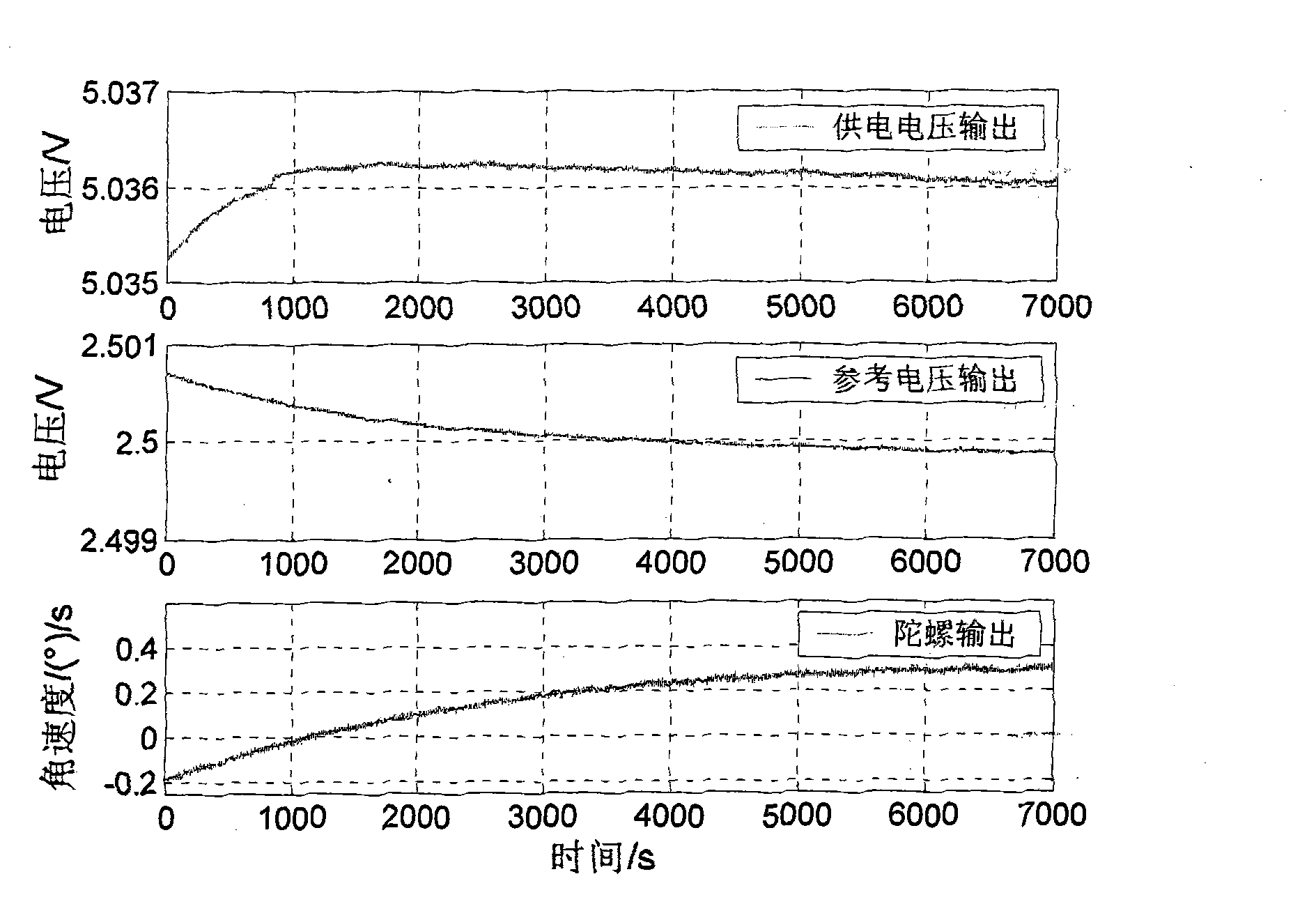
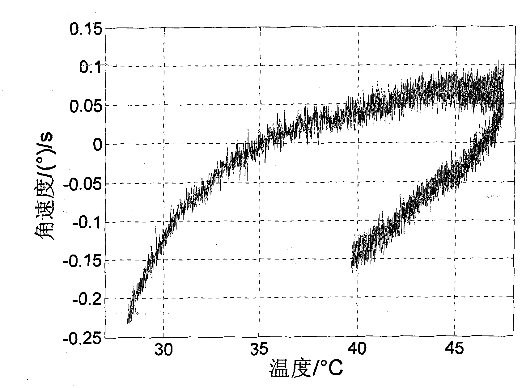
[0039] The output accuracy of the ADIS16130 MEMS gyro at room temperature is about 30° / h, and its output angular velocity will have a large drift with the external temperature. For every 1°C change in the external temperature, the resulting drift is about 125° / h; the gyro needs The power supply module is selected for power supply. When the power module produces a temperature drift of 1mv, the output signal of the gyro changes by 180° / h. In addition, the analog signal of the gyro needs to be AD converted before it can be used by the computer. The AD conversion circuit refers to the output voltage V of the voltage chip. ref Every change of 1mv will produce 360° / h gyro drift. Therefore, in order to ensure the use accuracy of the gyroscope, it is necessary to carry out precise temperature...

Embodiment 2

[0072] The specific implementation process of the present invention is described below by taking the temperature error compensation of the MS8002 accelerometer of Swiss colibrys company as an example.

[0073] The output accuracy of the MS8002 MEMS accelerometer at room temperature is about 0.05 mg, and its output bias will vary greatly with the external temperature. For every 1 °C change in the external temperature, the resulting zero bias is approximately 0.25 mg; the accelerometer needs to be selected The DC power module supplies power, and the output signal of the accelerometer will change by 0.5mg for every 1mv temperature drift generated by the power module. In addition, the analog signal of the accelerometer needs to be AD converted before it can be used by the computer. The AD conversion circuit refers to the output voltage V of the voltage chip. ref For every change of 1mv, 1mg of accelerometer zero bias will be introduced into the sampling results. Therefore, in ord...


PUM


Abstract

The invention relates to a method for compensating the temperature error of an inertial device. The method comprises the following steps of: performing analogue-to-digital (AD) sampling on the output voltage and the power supply voltage of the inertial device simultaneously and resolving the angular velocity information of a gyroscope (or acceleration information of an accelerometer) by using the ratio of two sampling values; and establishing a temperature error model of the angular velocity information (or the acceleration information) to compensate. The method has the advantages of eliminating the influences of temperature drifts of the power supply voltage of the inertial device and the reference voltage of an AD switching circuit on the output accuracy of the device, greatly simplifying the temperature error model of the inertial device and enhancing the temperature error compensation accuracy of the device.

Description

technical field [0001] The invention relates to a temperature error compensation method for inertial devices, which can be applied to temperature error modeling and compensation of inertial devices such as gyroscopes and accelerometers, and belongs to the field of inertial device testing, calibration, and error compensation, as well as the field of inertial navigation and integrated navigation main key technologies. technical background [0002] The inertial navigation system has the characteristics of full autonomy, high concealment, high bandwidth, and continuous output. It has strategic significance in national defense and is one of the most important equipment in the fields of aviation, aerospace, and navigation. [0003] The performance of inertial devices (gyroscopes and accelerometers) is the main factor affecting the accuracy of inertial navigation systems. 80% of inertial navigation system errors are caused by device errors. Therefore, improving the accuracy of iner...

Claims


Application Information

Patent Timeline
Patent Type & Authority Applications(China)
IPC IPC(8): G01C25/00G01P21/00
Inventor 徐烨烽张仲毅李魁杨国梁
Owner BEIHANG UNIV
Why Eureka
Try Eureka